$45
Epson Stylus Color 900 Service Manual - PDF DOWNLOAD
Epson Stylus Color 900 Service Manual - PDF DOWNLOAD
FILE DETAILS:
Epson Stylus Color 900 Service Manual - PDF DOWNLOAD
Language :English
Pages :200
Downloadable : Yes
File Type : PDF
IMAGES PREVIEW OF THE MANUAL:
DESCRIPTION:
Epson Stylus Color 900 Service Manual - PDF DOWNLOAD
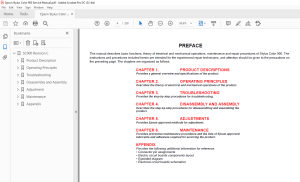
PREFACE
This manual describes basic functions, theory of electrical and mechanical operations, maintenance and repair procedures of Stylus Color 900. The
instructions and procedures in cluded herein are intended for the experienced repair technicians, and attention should be given to the precautions on
the preceding page. The chapters are organized as follows:
CHAPTER 1. PRODUCT DESCRIPTIONS
Provides a general overview and specifications of the product.
CHAPTER 2. OPERATING PRINCIPLES
Describes the theory of electrical and mechanical operations of the product.
CHAPTER 3. TROUBLESHOOTING
Provides the step-by-step procedures for troubleshooting.
CHAPTER 4. DISASSEMBLY AND ASSEMBLY
Describes the step-by-step procedures for disassembling and assembling the
product.
CHAPTER 5. ADJUSTMENTS
Provides Epson-approved methods for adjustment.
CHAPTER 6. MAINTENANCE
Provides preventive maintenance procedures and the lists of Epson-approved
lubricants and adhesives required for servicing the product.
APPENDIX
Provides the following additional information for reference:
• Connector pin assignments
• Electric circuit boards components layout
• Exploded diagram
• Electrical circuit boards schematics
TABLE OF CONTENTS:
Epson Stylus Color 900 Service Manual - PDF DOWNLOAD
Product Description
Features 10
Specifications 11
Printing Specifications 11
Options and Consumable Products 14
Paper Specifications 15
Cut Sheet 15
Transparency, Glossy Paper 15
Envelope 15
Index Card 15
Self Adhesive Sheets 15
Photo Paper 16
Photo Stickers 16
Printable Area 17
Ink Cartridge Specifications 19
Black Ink Cartridge 19
Color Ink Cartridge 20
Electrical Specifications 21
Environmental Condition 21
Reliability 22
Safety Approvals 22
Acoustic Noise 22
CE Marking (220 ~ 240 V version) 22
Physical Specifications 22
Interface 23
Parallel Interface (Forward Channel) 23
Parallel Interface (Reverse Channel) 26
Mac Serial Interface 28
USB Interface 29
Printer Language and Emulation 29
Prevention Hosts from Data Transfer time-out 29
Auto Interface Selection 29
IEEE 12844 Protocol 30
Control Panel Operation 31
Indicators (LEDs) 31
Panel Functions 32
Printer Setting Mode 32
Special Setting Mode 34
Printer Condition and Panel Status 35
Error Status 36
Ink Out 36
Paper Out 36
Paper Jam 36
No Ink Cartridge 36
Maintenance Request 36
Fatal Errors 36
Printer Initialization 37
Component Layout 38
Printer Mechanism 38
C265 Main Board 39
C265 PSB/PSE Board 41
C265 PNL Board 42
C265 Relay Board 42
Operating Principles
Overview 44
Printer Mechanism Operating Principles 44
Carriage Mechanism 46
Printing Mechanism 48
Paper Load Mechanism 49
Paper Feed Mechanism 51
Pump/ASF Switch Mechanism 52
Pump / Carriage Lock / Head Cleaner Mechanism 54
Electrical Circuit Operation Principles 56
C265 PSB/PSE Power Supply Board 56
C265Main Board 59
CR Motor Driver Circuit 67
PF Motor Driver Circuit 69
Pump/ASF Motor Driver Circuit 71
Printhead Driver Circuit 72
Cooling Fan Driver Circuit 74
ASF Solenoid Driver Circuit 76
EEPROM Control Driver Circuit 77
Troubleshooting
Overview 79
Troubleshooting with LED Error Indications 80
Remedies for Paper Out Error 81
Remedies for the Paper Jam Error 83
Remedies for No I/C and Ink Out Errors 85
Remedies for the Maintenance Error 87
Remedies for Fatal Error 88
Isolating the Faulty Part on the Power Supply Board 90
Isolating the Faulty Part according to the Phenomenon 92
Disassembly and Assembly
Overview 102
Precautions for Disassembling the Printer 102
Disassembly Procedures 104
Upper Case and Control Panel Removal 106
Printer Mechanism Removal 107
C265 Main Board Unit Removal 108
Relay Board and Cooling Fan Removal 109
Shield Plate on the C265 Main Board Removal 110
C265 PSB/PSE Board Removal 111
Printer Mechanism Disassembly 112
Printhead Removal 112
CR Motor Removal 114
PF Motor Removal 115
Pump/ASF Motor and Solenoid Removal 116
ASF Unit Removal 116
ASF Sensor Removal 121
CRHP Sensor Removal 122
PE Sensor Removal 122
Encoder Belt Sensor Removal 123
Carriage Unit Removal 124
Pump Unit Removal 125
Paper Eject Frame Removal 126
Paper Eject Roller Removal 126
Platen Removal 127
PF Roller Removal 128
Adjustment
Overview 131
Conditions for Each Adjustment 131
Adjustments 134
Preliminary Operation 134
Market Destination Check 136
Head Actuator Voltage Input 137
Head Angular Adjustment 141
Bi-Directional Adjustment 148
Printhead Cleaning Using the Program 153
Initial Ink Charge 154
Indication of the Counter Value for the Waste Ink Pad 155
Fan Check 157
Paper Gap Adjustment 158
Maintenance
Overview 162
Maintenance 162
Cleaning the Printhead 163
Maintenance Request Error 164
Lubrication and Adhesion 165
Lubricating the Carriage Guide Shaft 166
Appendix
Connector Summary 172
EEPROM ADDRESS MAP 176
Component Layout 180
Parts List 184
Exploded Diagrams 187
Circuit Diagrams 195
S.M 1/3/2025
More products