$35
Epson Stylus Color 980 Service Manual - PDF DOWNLOAD
Epson Stylus Color 980 Service Manual - PDF DOWNLOAD
FILE DETAILS:
Epson Stylus Color 980 Service Manual - PDF DOWNLOAD
Language :English
Pages :193
Downloadable : Yes
File Type : PDF
IMAGES PREVIEW OF THE MANUAL:
DESCRIPTION:
Epson Stylus Color 980 Service Manual - PDF DOWNLOAD
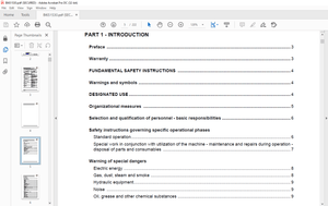
PREFACE
This manual describes basic functions, theory of electrical and mechanical operations, maintenance and repair procedures of Stylus Color 980. The instructions and procedures included herein are intended for the experienced repair technicians, and attention should be given to the precautions on the preceding page. The chapters are organized as follows:
CHAPTER 1. PRODUCT DESCRIPTIONS
Provides a general overview and specifications of the product.
CHAPTER 2. OPERATING PRINCIPLES
Describes the theory of electrical and mechanical operations of the product.
CHAPTER 3. TROUBLESHOOTING
Provides the step-by-step procedures for troubleshooting.
CHAPTER 4. DISASSEMBLY AND ASSEMBLY
Describes the step-by-step procedures for disassembling and assembling the
product.
CHAPTER 5. ADJUSTMENTS
Provides Epson-approved methods for adjustment.
CHAPTER 6. MAINTENANCE
Provides preventive maintenance procedures and the lists of Epson-approved
lubricants and adhesives required for servicing the product.
CHAPTER 7. APPENDIX
Provides the following additional information for reference:
• Connector pin assignments
• Electric circuit boards components layout
• Exploded diagram
• Electrical circuit boards schematics
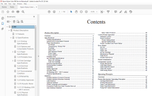
TABLE OF CONTENTS:
Epson Stylus Color 980 Service Manual - PDF DOWNLOAD
SC980 1
Product Description 8
11 Features 9
12 Specifications 10
121 Printing Specifications 10
122 Options and Consumable Products 13
123 Paper Specifications 15
1231 Cut Sheet 15
1232 Transparency, Glossy Film 15
1233 Envelope 15
1234 Index Card 15
1235 Self Adhesive Sheets 15
1236 Photo Paper 16
1237 Photo Stickers 16
124 Printable Area 17
125 Ink Cartridge Specifications 19
1251 Black Ink Cartridge 19
1252 Color Ink Cartridge 20
126 Electrical Specifications 21
127 Environmental Condition 21
128 Reliability 22
129 Safety Approvals 22
1210 Acoustic Noise 22
1211 CE Marking (220 ~ 240 V version) 22
1212 Physical Specifications 22
13 Interface 23
131 Parallel Interface (Forward Channel) 23
132 Parallel Interface (Reverse Channel) 26
133 USB Interface 28
134 Optional interface 28
135 Printer Language and Emulation 31
136 Prevention Hosts from Data Transfer time-out 31
137 Auto Interface Selection 31
1371 IEEE 12844 Protocol 32
14 Control Panel Operation 33
141 Indicators (LEDs) 33
142 Panel Functions 34
1421 Printer Setting Mode 34
1422 Special Setting Mode 36
143 Printer Condition and Panel Status 37
15 Error Status 38
151 Ink Out 38
152 Paper Out 38
153 Paper Jam 38
154 No Ink Cartridge 38
155 Maintenance Request 38
156 Fatal Errors 38
157 Double Feed Errors 38
16 Printer Initialization 39
17 Component Layout 40
171 Printer Mechanism 40
172 C380 Main Board 41
173 C265 PSB/PSE Board 43
174 C265 PNL Board 44
175 C265 Relay Board 44
Operating Principles 45
21 Overview 46
22 Printer Mechanism Operating Principles 46
221 Carriage Mechanism 48
222 Printing Mechanism 50
223 Paper Load Mechanism 51
224 Paper Feed Mechanism 53
225 Pump/ASF Switch Mechanism 54
226 Pump / Carriage Lock / Head Cleaner Mechanism 56
23 Electrical Circuit Operation Principles 58
231 C265 PSB/PSE Power Supply Board 58
232 C380Main Board 61
233 CR Motor Driver Circuit 69
234 PF Motor Driver Circuit 71
235 Pump/ASF Motor Driver Circuit 73
236 Printhead Driver Circuit 74
237 Cooling Fan Driver Circuit 76
238 ASF Solenoid Driver Circuit 78
239 EEPROM Control Driver Circuit 79
Troubleshooting 80
31 Overview 81
311 Troubleshooting with LED Error Indications 82
3111 Remedies for Paper Out Error 83
3112 Remedies for the Paper Jam Error 85
3113 Remedies for No I/C and Ink Out Errors 87
3114 Remedies for the Maintenance Error 89
3115 Remedies for Fatal Error 90
312 Isolating the Faulty Part on the Power Supply Board 92
313 Isolating the Faulty Part according to the Phenomenon 94
Disassembly and Assembly103
41 Overview104
411 Precautions for Disassembling the Printer104
42 Disassembly Procedures106
421 Upper Case and Control Panel Removal108
422 Printer Mechanism Removal109
423 C380 Main Board Unit Removal110
424 Relay Board and Cooling Fan Removal111
425 Shield Plate on the C380 Main Board Removal112
426 C265 PSB/PSE Board Removal113
427 Printer Mechanism Disassembly115
4271 Printhead Removal115
4272 CR Motor Removal117
4273 PF Motor Removal118
4274 Pump/ASF Motor and Solenoid Removal119
4275 ASF Unit Removal119
42751 ASF Disassembly120
4276 ASF Sensor Removal124
4277 CRHP Sensor Removal125
4278 PE Sensor Removal125
4279 Encoder Belt Sensor Removal126
42710 Carriage Unit Removal127
42711 Pump Unit Removal128
42712 Paper Eject Frame Removal129
42713 Paper Eject Roller Removal129
42714 Platen Removal130
42715 PF Roller Removal131
Adjustment133
51 Overview134
511 Conditions for Each Adjustment134
52 Adjustments137
521 Preliminary Operation137
522 Head Actuator Voltage Input139
523 Head ID Retrieval140
524 Head Angular Adjustment140
525 Bi-Directional Adjustment141
526 USB ID Input144
527 USB ID Retrieval145
528 Printhead Cleaning Using the Program146
529 Initial Ink Charge147
5210 Refurbishment for DOA147
5211 Indication of the Counter Value for the Waste Ink Pad148
5212 Fan Check150
5213 Paper Gap Adjustment151
Maintenance154
61 Overview155
611 Maintenance155
6111 Cleaning the Printhead156
6112 Maintenance Request Error157
62 Lubrication and Adhesion158
621 Lubricating the Carriage Guide Shaft159
Appendix164
71 Connector Summary165
72 EEPROM ADDRESS MAP169
73 Component Layout173
74 Parts List177
75 Exploded Diagrams180
76 Circuit Diagrams188
S.M 26/2/2025
More products