$45
Epson Stylus Color C70 - C80 Service Manual - PDF DOWNLOAD
Epson Stylus Color C70 - C80 Service Manual - PDF DOWNLOAD
FILE DETAILS:
Epson Stylus Color C70 - C80 Service Manual - PDF DOWNLOAD
Language :English
Pages :216
Downloadable : Yes
File Type : PDF
IMAGES PREVIEW OF THE MANUAL:
DESCRIPTION:
Epson Stylus Color C70 - C80 Service Manual - PDF DOWNLOAD
About This Manual
This manual describes basic functions, theory of electrical and mechanical operations, maintenance and repair procedures of the printer. The instructions and
procedures included herein are intended for the experienced repair technicians, and attention should be given to the precautions on the preceding page.
TABLE OF CONTENTS:
Epson Stylus Color C70 - C80 Service Manual - PDF DOWNLOAD
EPSON Stylus Color C70/C80 1
PRODUCT DESCRIPTION 9
11 FEATURES 10
12 SPECIFICATIONS 11
121 Physical Specification 11
122 Printing Specification 11
123 Paper Feeding 13
124 Input Data Buffer 13
125 Electric Specification 13
126 Environmental Condition 14
127 Reliability 14
128 Safety Approvals 14
129 Acoustic Noise 14
1210 CE Marking 14
13 INTERFACE 15
131 Parallel Interface 15
132 Parallel Interface (Reserve Channel) 17
133 USB Interface 18
134 Prevention Hosts of Data Transfer Time-out 19
135 Interface Selection 19
136 IEEE12844 Protocol 19
137 Printer Language and Emulation 20
1371 Control codes 20
1372 EPSON D4 control channel commands 21
14 OPERATOR CONTROLS 24
141 Operate Switch 24
142 Control Panel 24
1421 Switches 24
1422 Indicators 24
143 Panel Functions 25
144 Printer Condition and Panel Status 26
145 Printer setting mode (Stylus COLOR C80 only) 27
1451 Default setting mode 27
1452 Print head alignment mode 28
146 Printer Initialization 28
147 Errors 29
15 PAPER 30
151 Paper Handling 30
152 Paper Specification 30
1521 Cut Sheet 30
1522 Envelope 30
1523 Index Card 30
1524 EPSON special media 31
153 Printing Area 32
1531 Cut Sheet 32
1532 Envelopes 33
16 INK CARTRIDGE 34
161 Black Ink Cartridge 34
162 Color Ink Cartridge 34
Operating Principles 35
21 Overview 36
211 Printer Mechanism 36
212 Printhead 37
2121 Printing Process 37
2122 Printing Method 38
213 Carriage Mechanism 39
214 Paper Feeding Mechanism 40
215 Paper Loading Mechanism (ASF Unit) 41
216 Ink System Mechanism 49
2161 Pump Unit & Wiper mechanism 49
2162 Capping Mechanism 50
22 Electrical Circuit Operating Principles 51
221 C424 PSB/PSE board 51
222 C424 MAIN-B Board 54
2221 Main elements 55
2222 Printhead Driver Circuit 56
2223 CR / PF Motor (PF/ PUMP/ ASF Motor) Driver Circuit 57
2224 Reset Circuit 57
2225 EEPROM Control Circuit 58
2226 Sensor Circuit 58
Troubleshooting 60
31 Overview 61
311 Communication Error 62
312 Too Late Throughput 62
313 Status Monitor does not operate 63
314 Troubleshooting with LED Error Indications 64
3141 Remedy when a paper out, double feed or paper jam error occurs 66
3142 Remedies for No I/C and Ink Out Errors 71
3143 Countermeasures when an Ink Low indication appears 75
3144 Remedies for the Maintenance Error 75
3145 Remedies for Fatal Error 76
315 Isolating the Faulty Part on the Power Supply Board 79
316 Isolating the Faulty Part according to the Phenomenon 82
3161 PF Motor Driver Abnormal 1 83
3162 ASF Driver Abnormal 1 84
3163 Unexpected Ink Out Error 1 (During Print Operation) 85
3164 PF Motor Driver Abnormal 2 86
3165 Carriage Operation Abnormal 87
3166 Dot Missing 1 89
3167 Dot Missing 2 90
3168 Dot Missing 3 92
3169 Repair Handling Failure 93
31610 ASF Driver Abnormal 2 93
31611 CR Motor Operation Abnormal 95
Disassembly and Assembly 96
41 Overview 97
411 Precautions 97
412 Tools 98
413 Work Completion Check 99
414 Screws100
42 Disassembly101
421 Housing Removal102
4211 Printer Cover Removal102
4212 Stacker Assembly Removal102
4213 Upper Case Removal103
4214 Rear Cover Removal104
4215 Middle Housing Removal104
4216 Printer Mechanism Unit Removal105
4217 Waste Ink Pad Removal108
422 ASF Unit Removal108
423 Main Board Assembly Removal110
424 Power Supply Board Assembly Removal111
425 Print Head / Ink System Unit Removal113
426 Carriage Unit / CR Guide Shaft Removal116
427 Front Paper Guide Removal121
428 EJ Roller Unit Removal122
429 Motor Removal123
4291 PF Motor Removal123
4292 CR Motor Removal124
4210 PE Actuator Removal125
42101 Encoder Unit Board Removal125
4211 PF Roller Unit Removal126
4212 ASF Unit Disassembly127
42121 ASF Assembly Points132
4213 Rotary Encoder Removal134
Adjustment137
51 Overview138
511 Conditions for Each Adjustment138
52 Adjustment140
521 Setup the Adjustment Program140
522 Head ID Input141
523 Ink Charge143
524 Head Angle Adjustment144
525 Bi-D Adjustment149
526 PF Adjustment152
527 USB ID Readout (Checking)155
5271 Possible to Readout the Original USB ID (CASE 1)155
5272 Impossible to Readout the Original USB ID (CASE 2)157
528 EEPROM Initialization157
529 Platen Gap Adjustment (Mechanism Adjustment)159
5210 Head Cleaning Operation162
5211 Protection Counter Clear (and Check)163
5212 Top Margin Adjustment164
5213 First Dot Position Adjustment166
Maintenance169
61 Overview170
611 Cleaning170
612 Service Maintenance171
613 Lubrication and Adhesion172
614 Lubrication the Carriage Guide Shaft173
Appendix182
71 Connector Summary183
711 Major Component Unit183
712 EEPROM Address Map187
713 CSIC Address Map193
72 Component Layout196
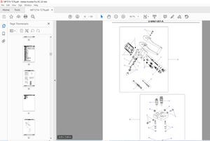
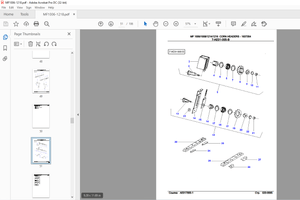
73 Exploded Diagram198
74 Parts List208
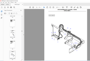
75 Electrical Circuits213
S.M 26/2/2025
More products