$44
Epson Stylus Photo 2000P service Manual - PDF DOWNLOAD
Epson Stylus Photo 2000P service Manual - PDF DOWNLOAD
FILE DETAILS:
Epson Stylus Photo 2000P service Manual - PDF DOWNLOAD
Language :English
Pages :178
Downloadable : Yes
File Type : PDF
IMAGES PREVIEW OF THE MANUAL:


DESCRIPTION:
Epson Stylus Photo 2000P service Manual - PDF DOWNLOAD
PREFACE
This manual describes basic functions, theory of electrical and mechanical operations, maintenance and repair procedures of EPSON Stylus
PHOTO 2000P. The instructions and procedures included herein are intended for the experienced repair technicians, and attention should
be given to the precautions on the preceding page. The chapters are organized as follows:
CHAPTER 1. PRODUCT DESCRIPTIONS
Provides a general overview and specifications of the product.
CHAPTER 2. OPERATING PRINCIPLES
Describes the theory of electrical and mechanical operations of the product.
CHAPTER 3. TROUBLESHOOTING
Provides the step-by-step procedures for troubleshooting.
CHAPTER 4. DISASSEMBLY AND ASSEMBLY
Describes the step-by-step procedures for disassembling and assembling the
product.
CHAPTER 5. ADJUSTMENTS
Provides Epson-approved methods for adjustment.
CHAPTER 6. MAINTENANCE
Provides preventive maintenance procedures and the lists of Epson-approved
lubricants and adhesives required for servicing the product.
APPENDIX
Provides the following additional information for reference:
• Connector Summary
• EEPROM Address Map
• Circuit Board Component Layout
• Exploded Diagrams
• Parts List
• Electrical Board Circuit Diagrams
TABLE OF CONTENTS:
Epson Stylus Photo 2000P service Manual - PDF DOWNLOAD
Product Descriptions 9
11 General Characteristics 10
12 Printing specification 11
121 Printing specification 11
122 Paper feeding 11
123 Input data buffer 12
124 Electric specification 12
125 Environmental condition 13
126 Reliability 14
127 Safety Approvals 14
128 Acoustic noise 14
129 CE Marking 14
13 Interface 15
131 Hardware interface 15
1311 Parallel interface 15
1312 Parallel Interface (Reverse Channel) 18
1313 USB interface 19
1314 Prevention Hosts from Data Transfer Time-out 20
1315 Interface Selection 20
1316 IEEE12844 protocol 20
14 Operator Controls 21
141 Buttons 21
142 LED Indicators 21
143 Panel Functions 22
144 Special Setting Mode 22
145 Printer Condition and Panel Status 23
146 Errors 23
147 Printer Initialization 24
15 Paper 25
151 Paper handling 25
152 Paper specification 25
1521 Cut Sheet 25
1522 Envelope 25
1523 EPSON special media 25
16 Printing area 27
161 Cut Sheet 27
1611 Envelopes 28
17 Ink cartridge 29
171 Black ink cartridge 29
172 Color ink cartridge 29
18 Physical specification 30
OPERATING PRINCIPLES 31
21 Overview 32
211 Printer Mechanism 32
212 Ink 33
2121 Comparison between Pigment Ink and Dye Ink 33
2122 Drop of Pigment Ink and Dye Ink 33
213 Printhead Mechanism 34
214 Carriage Mechanism 35
2141 Carriage Motor (CR Motor) 35
2142 Platen Gap (PG) /Parallelism Adjustment Mechanism 36
2143 Carriage Home Position (HP) Detection 36
215 Paper Feeding Mechanism 36
2151 CR Lock Mechanism 38
216 Paper Loading Mechanism 39
2161 Drive Transmission to the ASF Unit 39
2162 Paper Loading Operation 40
2163 Pump Mechanism 41
2164 Capping Mechanism 42
22 Electrical Circuit Operating Principles 43
221 C298PSB/PSE Board 43
2211 Electrical Circuit 43
2212 Protection Circuits 45
2213 Power Supply Control Function 45
2214 Energy Save Mode 45
222 C304MAIN Board Circuit Operation Principles 46
2221 Printhead Driver Circuit 48
2222 Reset Circuit 49
2223 Motor Driver Circuit 49
2224 ASF/Pump Motor Driver Circuit 52
2225 EEPROM Control Circuit 53
2226 Sensor Circuit 53
TROUBLESHOOTING 55
31 Overview 56
311 Self-Diagnostic Function 57
3111 Troubleshooting with LED Error Indicators 57
3112 Error Conditions 58
3113 Remedies for Paper Out Error 60
3114 Remedies for the Paper Jam Error 62
3115 Remedies for No Ink Cartridge Error/Ink Cartridge Problem 63
3116 Remedies for Maintenance Request Error 63
3117 Remedies for Fatal Error 64
312 Isolating the Faulty Part on the Power Supply Board 67
313 Isolating the Faulty Part according to the Phenomenon 69
32 FAQ 73
DISASSEMBLY AND ASSEMBLY 75
41 Overview 76
411 Precaution for Disassembling the Printer 76
412 Tools 77
413 Specifications for Screws 78
414 Service Checks After Repair 79
42 Disassembly Procedures 80
421 HOUSING Removal 81
422 Circuit Board Assembly Removal 82
423 Panel Unit Removal 85
424 Printhead Unit Removal 87
425 TRAY, ABSORBER ASSEMBLY Removal 89
426 Ink Unit Removal 91
427 MOTOR ASSEMBLY, CR Removal 94
428 MOTOR ASSEMBLY, ASF Removal 95
429 DE Unit Removal 96
4210 ASF Unit Removal 99
42101 SHAFT, ROLLER, LD Removal101
42102 ROLLER ASSEMBLY, LD, RIGHT/LEFT Removal106
4211 Carriage Unit Removal107
4212 BOARD ASSEMBLY, ENCODER Removal109
4213 ROLLER, PF Removal110
42131 SCALE, PF Installation113
4214 MOTOR ASSEMBLY, PF Removal116
4215 PE Sensor Unit Removal117
ADJUSTMENT118
51 Overview119
511 Adjustment Items119
512 Adjustment Tools120
52 Adjustment121
521 Parallelism Adjsutment121
522 Backlash Adjsutment123
523 Using the Adjustment Program125
5231 About the Adjustment Program125
5232 How to Install the Program125
5233 How to Uninstall the Program125
5234 Starting the Adjustment Program126
524 Head voltage ID input126
5241 Where to Find the Head ID126
5242 Check Present Data127
5243 Change Data127
525 Head angular adjsutment128
526 Bi-Directional adjustment130
527 USB ID check/input132
5271 Inputting/Checking the USB ID132
528 Head cleaning133
529 Initial ink charge134
5210 Protection counter check134
52101 Check the Present Counter Value134
52102 Clear the Protection Counter Values135
5211 CSIC information136
5212 Print A4 pattern137
52121 Recovery Routine137
MAINTENANCE138
61 Overview139
611 Cleaning139
612 Service Maintenance139
6121 Head Cleaning139
6122 Paper Eject Roller Cleaning140
6123 ASF Roller Cleaning141
6124 Maintenance Request Error Clear142
613 Lubrication142
APPENDIX148
71 Connector Summary149
711 Connector Pin Assignment149
72 EEPROM Address Map153
73 Circuit Board Component Layout157
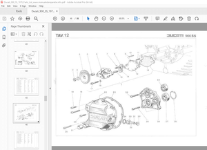
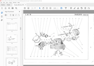
74 Exploded Diagrams160
75 Parts List168
76 Electrical Circuit Board Diagrams174
S.M 28/2/2025
More products