$40
Epson Stylus Photo 870 - 1270 Service Manual SEIJ9901 - PDF DOWNLOAD
Epson Stylus Photo 870 - 1270 Service Manual SEIJ9901 - PDF DOWNLOAD
FILE DETAILS:
Epson Stylus Photo 870 - 1270 Service Manual SEIJ9901 - PDF DOWNLOAD
Language :English
Pages :182
Downloadable : Yes
File Type : PDF
IMAGES PREVIEW OF THE MANUAL:
DESCRIPTION:
Epson Stylus Photo 870 - 1270 Service Manual SEIJ9901 - PDF DOWNLOAD
PREFACE
This manual describes basic functions, theory of electrical and mechanical operations, maintenance and repair procedures of EPSON Stylus
PHOTO 870/1270. The instructions and procedures included herein are intended for the experienced repair technicians, and attention
should be given to the precautions on the preceding page. The chapters are organized as follows:
CHAPTER 1. PRODUCT DESCRIPTIONS
Provides a general overview and specifications of the product.
CHAPTER 2. OPERATING PRINCIPLES
Describes the theory of electrical and mechanical operations of the product.
CHAPTER 3. TROUBLESHOOTING
Provides the step-by-step procedures for troubleshooting.
CHAPTER 4. DISASSEMBLY AND ASSEMBLY
Describes the step-by-step procedures for disassembling and assembling the
product.
CHAPTER 5. ADJUSTMENTS
Provides Epson-approved methods for adjustment.
CHAPTER 6. MAINTENANCE
Provides preventive maintenance procedures and the lists of Epson-approved
lubricants and adhesives required for servicing the product.
APPENDIX
Provides the following additional information for reference:
• EEPROM Address Map
• Connector Pin Assignments
• Component Layout
• Exploded Diagrams
• Electrical Board Circuit Diagrams
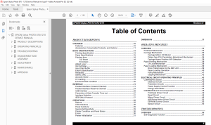
TABLE OF CONTENTS:
Epson Stylus Photo 870 - 1270 Service Manual SEIJ9901 - PDF DOWNLOAD
PRODUCT DESCRIPTIONS
OVERVIEW 10
Features 10
Accessories, Consumable Products, and Options 11
BASIC SPECIFICATIONS 13
Printing Specification 13
Paper Specifications 15
Printing Area 16
Cut Sheet 16
Envelopes 17
Adjust Lever 17
Ink Cartridge 17
Input Data Buffer 18
Electric Specification 18
Reliability 19
Safety, EMC 19
Acoustic Noise 19
CE marking 19
Environmental Condition 20
INTERFACE 21
Parallel Interface (Forward Channel) 21
Parallel Interface (Reserve Channel) 24
USB Interface 26
Prevention of Data Transfer Time-out 27
Interface Selection 27
IEEE12844 Protocol 27
OPERATIONS 28
Buttons 28
LED Indicators 28
Panel Functions 29
Special Setting Mode 29
Printer Condition and Panel Status 30
Errors 30
Printer Initialization 31
DIMENSION 31
OPERATING PRINCIPLES
OVERVIEW 33
Printhead Mechanism 34
Carriage Mechanism 35
Carriage Motor (CR Motor) 35
Platen Gap (PG) /Parallelism Adjustment Mechanism 36
Carriage Home Position (HP) Detection 36
Paper Feeding Mechanism 36
CR Lock Mechanism 38
Paper Loading Mechanism 39
Drive Transmission to the ASF Unit 39
Paper Loading Operation 40
Pump Mechanism 41
Capping Mechanism 42
ELECTRICAL CIRCUIT OPERATING PRINCIPLES 43
C298PSB/PSE Board 43
Electrical Circuit 43
Protection Circuits 45
Power Supply Control Function 45
Energy Save Mode 45
C304MAIN Board Circuit Operation Principles 46
Printhead Driver Circuit 48
Reset Circuit 49
Motor Driver Circuit 49
ASF/Pump Motor Driver Circuit 52
EEPROM Control Circuit 53
Sensor Circuit 53
TROUBLESHOOTING
OVERVIEW 56
Self-Diagnostic Function 57
Troubleshooting with LED Error Indicators 57
Error Conditions 58
Remedies for Paper Out Error 60
Remedies for the Paper Jam Error 62
Remedies for No Ink Cartridge Error/Ink Cartridge Problem 63
Remedies for Maintenance Request Error 63
Remedies for Fatal Error 64
Isolating the Faulty Part on the Power Supply Board 67
Isolating the Faulty Part according to the Phenomenon 69
DISASSEMBLY AND ASSEMBLY
OVERVIEW 74
Precaution for Disassembling the Printer 74
Tools 75
Specifications for Screws 76
Service Checks After Repair 77
DISASSEMBLY PROCEDURES 78
HOUSING Removal 79
Circuit Board Assembly Removal 80
Panel Unit Removal 83
Printhead Unit Removal 85
TRAY, ABSORBER ASSEMBLY Removal 87
Ink Unit Removal 89
MOTOR ASSEMBLY, CR Removal 92
MOTOR ASSEMBLY, ASF Removal 93
DE Unit Removal 94
ASF Unit Removal 97
SHAFT, ROLLER, LD Removal 99
ROLLER ASSEMBLY, LD, RIGHT/LEFT Removal 104
Carriage Unit Removal 105
BOARD ASSEMBLY, ENCODER Removal 107
ROLLER, PF Removal 108
SCALE, PF Installation 111
MOTOR ASSEMBLY, PF Removal 114
PE Sensor Unit Removal 115
ADJUSTMENT
OVERVIEW 117
Adjustment Items 117
Adjustment Tools 118
ADJUSTMENT 119
Parallelism Adjsutment 119
Backlash Adjsutment 121
Using the Adjustment Program 123
About the Adjustment Program 123
How to Install the Program 123
How to Uninstall the Program 123
Starting the Service Program 124
Market destination check 125
Head voltage ID input 126
Where to Find the Head ID 126
Check Present Data 126
Change Data 127
Head angular adjsutment 128
Bi-Directional adjustment 130
USB ID check/input 132
Inputting/Checking the USB ID 132
Head cleaning 134
Initial ink charge 135
Protection counter check 135
Check the Present Counter Value 135
Clear the Protection Counter Values 136
CSIC information 137
Print A4 pattern 137
MAINTENANCE
OVERVIEW 139
Cleaning 139
Service Maintenance 139
Head Cleaning 139
Maintenance Request Error Clear 139
Lubrication 140
APPENDIX
CONNECTOR SUMMARY 147
Connector Pin Assignment 147
EEPROM ADDRESS MAP 151
CIRCUIT BOARD COMPONENT LAYOUT 155
EXPLODED DIAGRAMS 158
Exploded Diagrams for Stylus PHOTO 870 158
Exploded Diagrams for Stylus PHOTO 1270 164
PARTS LIST 170
Parts List for Stylus PHOTO 870 170
Parts List for Stylus PHOTO 1270 174
ELECTRICAL CIRCUIT BOARD DIAGRAMS 178
S.M 26/2/2025
More products