$35
Epson Stylus Pro 5000 Service Manual - PDF DOWNLOAD
Epson Stylus Pro 5000 Service Manual - PDF DOWNLOAD
FILE DETAILS:
Epson Stylus Pro 5000 Service Manual - PDF DOWNLOAD
Language :English
Pages :235
Downloadable : Yes
File Type : PDF
IMAGES PREVIEW OF THE MANUAL:
DESCRIPTION:
Epson Stylus Pro 5000 Service Manual - PDF DOWNLOAD
PREFACE
This manual describes basic functions, theory of electrical and mechanical operations, maintenance and repair procedures of Stylus Pro5000. The
instructions and procedures included herein are intended for the experienced repair technicians, and attention should be given to the precautions on the
preceding page. The chapters are organized as follows:
CHAPTER 1. PRODUCT DESCRIPTIONS
Provides a general overview and specifications of the product.
CHAPTER 2. OPERATING PRINCIPLES
Describes the theory of electrical and mechanical operations of the product.
CHAPTER 3. TROUBLESHOOTING
Provides the step-by-step procedures for troubleshooting.
CHAPTER 4. DISASSEMBLY AND ASSEMBLY
Describes the step-by-step procedures for disassembling and assembling the
product.
CHAPTER 5. ADJUSTMENTS
Provides Epson-approved methods for adjustment.
CHAPTER 6. MAINTENANCE
Provides preventive maintenance procedures and the lists of Epson-approved
lubricants and adhesives required for servicing the product.
APPENDIX
Provides the following additional information for reference:
• Connector pin assignments
• Electric circuit boards components layout
• Exploded diagram
• Electrical circuit boards schematics
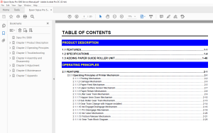
TABLE OF CONTENTS:
Epson Stylus Pro 5000 Service Manual - PDF DOWNLOAD
Styus Pro 5000 0
Chapter 1 Product Description 10
11 FEATURES 11
12 SPECIFICATIONS 13
SERIAL INTERFACE 17
PARALLEL INTERFACE 17
CONTROL PANEL 21
PANEL SETTING FUNCTION 26
13 ADDING PAPER GUIDE ROLLER UNIT 35
Chapter 2 Operating Principles 37
21 FEATURE 38
211 Operating Principles of Printer Mechanism 38
2111 Printing Mechanism 39
2112 Carriage Mechanism 40
2113 Paper Feed Mechanism 42
2114 Upper Surface Sensor Mechanism 44
2115 Paper Return Mechanism 45
2116 Lifter Gear Train Mechanism 46
2117 Hopper 5mm Down Mechanism 47
2118 Sub Roller Gear Train Mechanism 50
2119 Gear Train Change with Hopper installed 51
21110 Ink Engage/ Disengage Mechanism 53
21111 PG Disengage Mechanism 55
21112 Ink Valve Mechanism 57
21113 Friction Release Mechanism 58
21114 Gear Train Block Diagram 60
212 Outline of Electrical Circuit 61
2121 C228 PSB Board 61
2122 C228 DRV Board 63
2123 C228 Main Board 64
Chapter 3 Troubleshooting 65
31 FEATURES 66
311 Problems relating to the printer mechanism 66
Chapter 4 Assembly and Disassembly 0
41 OVERVIEW 0
411 Precautions 0
412 Tools 0
413 Screws 0
42 DISASSEMBLY 0
421 Housing Upper Removal 0
422 Housing Front Unit Removal 0
423 Mechanism Unit Removal 0
424 MB Rear Unit Removal 0
425 Disassembling the Mechanism 0
4251 Discharge Brush Removal 0
4252 Paper Guide Assembly, Cover Removal 0
4253 Print Head Removal 0
4254 MB Front Unit Removal 0
4255 Fan Assembly Removal 0
4256 PS Unit Removal 0
4257 Motor Assembly, PF Removal 0
4258 Motor Asssembly, CR Removal 0
4259 Motor Assembly, ASF Removal 0
42510 Carriage Unit Removal 0
42511 Frame, Main, Paper Eject Removal 0
42512 Paper Guide Upper Unit Removal 0
42513 Pump Frame Removal 0
42514 Frame, Main, PF Removal 0
42515 ASF Unit Removal 0
42516 Upper Surface Sensor Removal 0
42517 PE Sensor Removal 0
42518 PR Sensor Removal 0
42519 HP Sensor Removal 0
42520 Cable Assembly, Sensor FPC Removal 0
42521 Interlock Assembly Removal 0
43 DISASSEMBLY AND ASSEMBLY FOR GEAR 0
431 Disassembly of Gear Train 0
432 Assembling Gear Train 0
Chapter 5 Adjustment168
51 OVERVIEW169
511 Conditions which adjustment is required169
5111 Resetting Initial Ink Charge Flag171
5112 Re- input the Model Name174
5113 Head Voltage Value Adjustment176
5114 Head Angular Adjustment179
5115 Head Height Adjustment186
5116 Head Gap Adjustment190
5117 Bi-D Adjustment195
5118 Uploading of Firmware200
5119 Parallelism Adjustment202
51110 Upper Surface Sensor Positioning Adjustment205
Chapter 6 Maintenance207
61 CLEANING208
62 MAINTENANCE209
621 Head cleaning209
622 Maintenance Request210
63 LUBRICATION AND ADHESION211
Chapter 7 Appendix217
71 CONNECTOR SUMMARY218
72 EEPROM ADDRESS MAP222
73 COMPONENT LAYOUT227
74 CIRCUIT DIAGRAM 0
S.M 28/2/2025
More products