$40
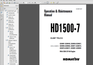
Epson Stylus Pro 9000 Service Manual - PDF DOWNLOAD
Epson Stylus Pro 9000 Service Manual - PDF DOWNLOAD
FILE DETAILS:
Epson Stylus Pro 9000 Service Manual - PDF DOWNLOAD
Language :English
Pages :186
Downloadable : Yes
File Type : PDF
IMAGES PREVIEW OF THE MANUAL:


TABLE OF CONTENTS:
Epson Stylus Pro 9000 Service Manual - PDF DOWNLOAD
Stylus Pro 9000 / RevB 1
Precautions 3
Revision Status 4
Contents 5
Product Description 9
11 Features 10
111 Professional Color Printing Features 10
112 Consumable Products & Options 11
12 Specifications 12
Print Specifications 12
Paper-Feed Specifications 12
Paper Specifications 13
Electrical Specifications 16
Conformity/Safety Approvals 16
Reliability 16
Environmental Specifications 17
Ink Cartridge Specifications 18
Acoustic Noise 18
Controller Specifications 18
Cutter Specifications 18
Printer Dimensions & Weight 19
13 Control Panel 19
Buttons 20
LED indicators 20
131 Control Panel Messages 21
132 Control Panel Settings 22
SelecType menu 22
Test Print Menu 23
Printer Status Menu 23
User Paper Settings 23
Cutter Replacement Menu 24
Gap Adjustment Menu 24
133 Maintenance Errors 24
134 Service Errors 25
135 Service Related Printer Settings 26
Maintenance Mode 26
Maintenance Mode 2 26
Self-Diagnostic Mode 26
136 Firmware Update 27
Updating the Firmware via the PC 27
Updating the Firmware Via Memory Card 27
137 Jumper Settings 27
14 Interfaces 28
Serial interface 28
Parallel interface 29
TYPE-B Optional interface 31
Buffer operation 31
15 Initialization 32
16 Interface selection 32
Operating Principles 33
21 Component List & Illustrations 34
211 Print Mechanism Components 34
Carriage Components 35
Paper Feed Path & Components 35
Ink System Components 36
Electrical Circuit Boards 36
22 Description of Components 37
221 Carriage Mechanism 37
CR Guide Rail 37
Carriage 38
222 Paper Feed Assembly 40
PF Rail 40
Sensors 41
223 Cleaning Mechanism 42
224 Ink Supply Mechanism 43
Sensors 44
23 Printer Mechanism Operation Outline 46
Carriage Mechanism 46
Platen Gap Mechanism 46
Paper Feed Mechanism 47
24 Summary of Control Circuit Operations 51
241 Reset Circuit 52
242 CR/PF Motor Driver Circuit 52
243 Head SLID Motor Driver Circuit 53
244 Pump Motor Driver Circuit 53
245 Printhead Driver Circuit 54
246 Sensors 55
Troubleshooting 56
31 Outline 57
311 Test Points 57
32 Troubleshooting Using the Error Messages 57
321 Errors that require a service technician 59
Maintenance Req 0100 59
Service Req 00000100 59
Service Req 00000101 59
Service Req 00010000 59
Service Req 00010001 59
Service Req 00010002 60
Service Req 00010003 60
Service Req 00010004 60
Service Req 00010005 60
Service Req 00010006 61
Service Req 00010007 61
Service Req 00010008 61
Service Req 00010009 61
Service Req 0001000A 61
Service Req 0001000C 61
Service Req 0001000D Service Req 0001000E 61
Service Req 0001000F 62
Service Req 00010010 62
Service Req 00020000 (NVRAM error) Service Req 00020001 (Internal RAM error) Service Req 00020 62
Service Req 10000004 (CPU gnrl illegal Instrctns) Service Req 10000006 (CPU Slot illegal Instrc 62
322 General Errors 63
Ink Low 63
Paper Out 63
Load xxx Paper 63
Load Paper 63
Paper Jam 64
Cover Open 64
Paper Not Cut 64
Paper Not Straight 64
Reload Paper 65
Push Lever Down 65
Compartment Open 65
Ink Out 66
No Ink Cartridge 66
Remove Paper 66
Option I/F Error 66
33 Troubleshooting Based on Your Printout 67
Dot Missing 67
Uneven Printing/Poor Resolution 68
Smudged or Marred Printout (Front) 68
Smudged or Marred Printout (Reverse side) 68
White or Black Banding 68
Disassembly & Assembly 69
41 Summary 70
411 Warnings 70
412 Tools 71
413 Screw List 71
42 Disassembly Flow 72
421 Removing the Housing 73
Maintenance Cover Removal 73
H Top Cover Removal 74
L/R Side Covers Removal 75
Front Cover Assembly Removal 76
Roll Cover Assembly Removal 77
Lower Paper Guide Removal 78
Upper Paper Guide Removal 79
422 Circuit Board Removal 80
Power Board Removal 80
C277MAIN Board Removal 81
423 Printer Mechanism Disassembly 82
Replacing the Waste Ink Pads 83
Replacing the Printheads 85
Removing the CR Motor/Pulley Assembly 88
Removing the PF Motor Assembly 89
removing the hd_SLID motor assembly 90
Maintenance Assembly Removal & Disassembly 91
removing the INterlock switch (L/R) 93
removing the P_THICK SENSOR 94
removing the P_REAR Sensor 94
removing the P_FRONT sensor 95
removing the LEVER POSITION SENSOR / hd_SLID HP sensor 95
removing the CR-HP sensor and encoder 96
424 Ink System Machanism Disassembly 98
4241 Removing the I/C Holder Assembly 98
4242 Disassembling the I/C Holder105
Adjustment106
51 Summary107
511 Caution107
512 Adjustment Tools107
513 Adjustment Items108
52 Adjustment Steps110
521 Parameter Backup110
Requirements for Backup110
Backup & Download Procedures110
Other/Notes111
522 Firmware Update112
Updating Via the PC112
Updating From a Memory Card112
523 Self-Diagnostics113
5231 Entering Self-Diagnostic Mode113
5232 Self-Diagnostic Mode Menus114
524 Adjustment Menu115
Adj Cap Position117
Adj Check Skew117
Adj Input Rank118
Adj Check Nozzle119
Adj x Head Slant (B/C heads)120
Adj B/C Head Height121
Adj Bi-D122
Head Gap Adjustment124
Flush Point Right and Left Adjustment125
Feed Adjustment126
Adj Top & Bottom127
Adj Rear Sensor Position128
Test Pattern Print129
Clean Head (drain ink)129
Counter Clear130
525 Test Menu131
Version132
Control Panel132
Sensors133
Sensor Adjustment134
Encoder135
Fan135
Elec135
526 Cleaning menu137
Print menu137
527 Parameter menu137
"Initialize" Items137
"Update" Items138
528 Mechanism Adjustment138
Carriage Cover Height Adjustment139
Cutter Position Adjustment140
CR Steel Belt Tension Adjustment141
PF Belt Tension Adjustment141
Gear Backlash Adjustment142
I/H Lever Position Adjustment142
P THICK Sensor Assembly Adjustment143
Cover R/L Sensor Assembly144
Maintenance & Setup145
61 General Maintenance Issues146
611 Periodic Maintenance Items147
612 Product Life Information147
613 Important Maintenance Items During Service Operations148
614 Lubrication148
62 Unpacking and Installing149
621 The Packaging149
Before Opening the Large & Medium boxes149
622 Contents of the Packaging150
Medium-size box150
Large box150
623 Unpacking and Assembling151
From unpacking to assembling the Stand151
Assembling the Printer body154
Appendix158
71 Wiring Diagrams159
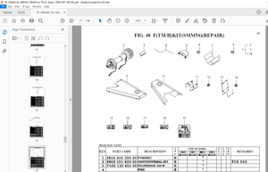
72 Parts List161
73 Exploded View Diagram167
74 Component Layout182
75 Circuit Diagrams184
S.M 28/2/2025
More products