$45
Epson Terminal Printer DFX-5000+ Service Manual - PDF DOWNLOAD
Epson Terminal Printer DFX-5000+ Service Manual - PDF DOWNLOAD
FILE DETAILS:
Epson Terminal Printer DFX-5000+ Service Manual - PDF DOWNLOAD
Language :English
Pages :186
Downloadable : Yes
File Type : PDF
IMAGES PREVIEW OF THE MANUAL:
DESCRIPTION:
Epson Terminal Printer DFX-5000+ Service Manual - PDF DOWNLOAD
PREFACE
This manual describes functions, theory of electrical and mechanical operations, maintenance, and repair
of DFX-5000+.
The instructions and procedures included herein are intended for the experience repair technician, and
attention should be given to the precautions on the preceding page. The chapters are organized as
follows:
CHAPTER 1. GENERAL DESCRIPTION
Provides a general product overview, lists specifications, and illustrates the main components of the printer.
CHAPTER 2. OPERATING PRINCIPLES
Describes the theory of printer operation.
CHAPTER 3. DISASSEMBLY AND ASSEMBLY
Includes a step-by-step guide for product disassembly and assembly.
CHAPTER 4. ADJUSTMENTS
Includes a step-by-step guide for adjustment.
CHAPTER 5. TROUBLESHOOTING
Provides Epson-approved techniques for adjustment.
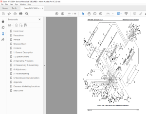
CHAPTER 6. MAINTENANCE AND LUBRICATION
Describes preventive maintenance techniques and lists Lubricants and adhesives required to service the equipment.
APPENDIX
Describes connector pin assignments, circuit diagrams, circuit board component layout and exploded diagram.
TABLE OF CONTENTS:
Epson Terminal Printer DFX-5000+ Service Manual - PDF DOWNLOAD
Table of Contents
11 GENERAL FEATURES 1-1
12 SPECIFICATIONS 1-3
Printer Capabilities l-3
Paper Handling Specifications l-3
Paper Specifications 1-5
Ribbon Specifications 1-12
Environmental Conditions 1-12
Electrical Specifications 1-13
Reliability 1-13
Safety Approvals 1-13
Physical Specifications 1-13
13 INTERFACE SPECIFICATIONS 1-14
131 Parallel Interface 1-14
132 RS-232C Serial interface 1-16
14 PRINTER OPERATION 1-17
Control Panel 1-17
Self-test 1-18
Hexadecimal Dump Function 1-18
Paper Out Detection Function 1-18
Cover Open Detection 1-18
Paper Width Detection 1-19
Automatic PaperThickness Adjustment 1-19
Paper Memory Function 1-19
1481 Using the Paper Memory Function 1-20
1482 Saving Paper Format and Thickness Information 1-20
Automatic Tear Off Function 1-21
PaperJam Detection 1-21
Automatic Interface Selection 1-21
Thermal Protection 1-21
Skip Binding Function 1-22
Printer Initialization 1-22
Buzzer Operation 1-22
15 DIP SWITCH SETTINGS 1-23
16 MAIN COMPONENTS 1-26
161 M-3C11 Printer Mechanism 1-27
Main Control Board (Cl 17 MAIN Board Assembly) 1-28
Power Supply Circuit (C117 PSB/PSE Board Assembly) 1-28
Control Panel Board (C117 PNL Board Assembly) 1-29
Housing 1-29
List of Figures
Exterior View of the DFX-5000+ 1-1
Pin Configuration 1-3
Printable Area for Fanfold Paper 1-5
Unsuitable Paper 1-6
Form Override Area 1-6
Figure 1-6 Perforation Pitch 1-6
Figure l-7 Paper Edge at a Horizontal Perforation 1-7
Figure l-8 Perforation Intersections 1-7
Figure l-9 Raised Portion at aPerforation 1-7
Figure 1-10 Sprocket Holes 1-7
Figure 1-11 Aligned Sprocket Holes 1-7
Figure 1-12 Incorrectly Folded Paper 1-8
Figure 1-13 Printable Area, Overlapping Multi-part Forms 1-8
Figure 1-14 Dotted Paste Positions 1-9
Figure 1-15 Stapled Area 1 1-9
Figure 1-16 Stapled Area 2 1-9
Figure 1-17 Stapled Area 3 1-10
Figure 1-18 Correct Multi-part Form Binding 1-10
Figure 1-19 Printable Area for Fanfold Paper with a Label 1-10
Figure 1-20 Printable Area for Labels 1-11
Figure 1-21 Label and Carrier 1-12
Figure 1-22 Data Transmission Timing 1-14
Figure 1-23 Control Panel 1-17
Figure 1-24 Multi-part Forms with a Label 1-19
Figure 1-25 overlapping Multi-part Forms 1-19
Figure 1-26 Main Components 1-26
Figure 1-27 M-3C11 Printer Mechanism 1-27
Figure 1-28 C117 MAIN Board Assembly 1-28
Figure 1-29 C117 PSB/PSE Board Assembly 1-28
Figure 1-30 C117 PNL Board Assembly 1-29
Figure 1-31 Housing 1-29
List of Tables
Table 1-1 Options and Consumables 1-2
Table 1-2 Character Size and Pitch 1-3
Table 1-3 Printing Speeds 1-4
Table 1-4 Character Tables 1-4
Table 1-5 Acceptable Environmental Conditions 1-12
Table 1-6 Rated Electrical Ranges 1-13
Table 1-7 Parallel lnterface Signals and Connector Pin Assignments 1-15
Table 1-8 Serial Interface Signals and Connector Pin Assignments 1-16
Table 1-9 Selecting the Paper Memory Area 1-20
Table 1-10 Setting the Page Length 1-20
Table 1-11 Setting the Paper Type 1-21
Table 1-12 DIP Switch Settings 1-23
Table 1-13 IBM Mode Selection 1-23
Table 1-14 ESC/P Mode Selection 1-24
Table 1-15 Interface Selection 1-25
Table 1-16 Baud Rate Selection 1-25
Table 1-17 Page Length Selection 1-25
S.M 28/2/2025
More products