$42
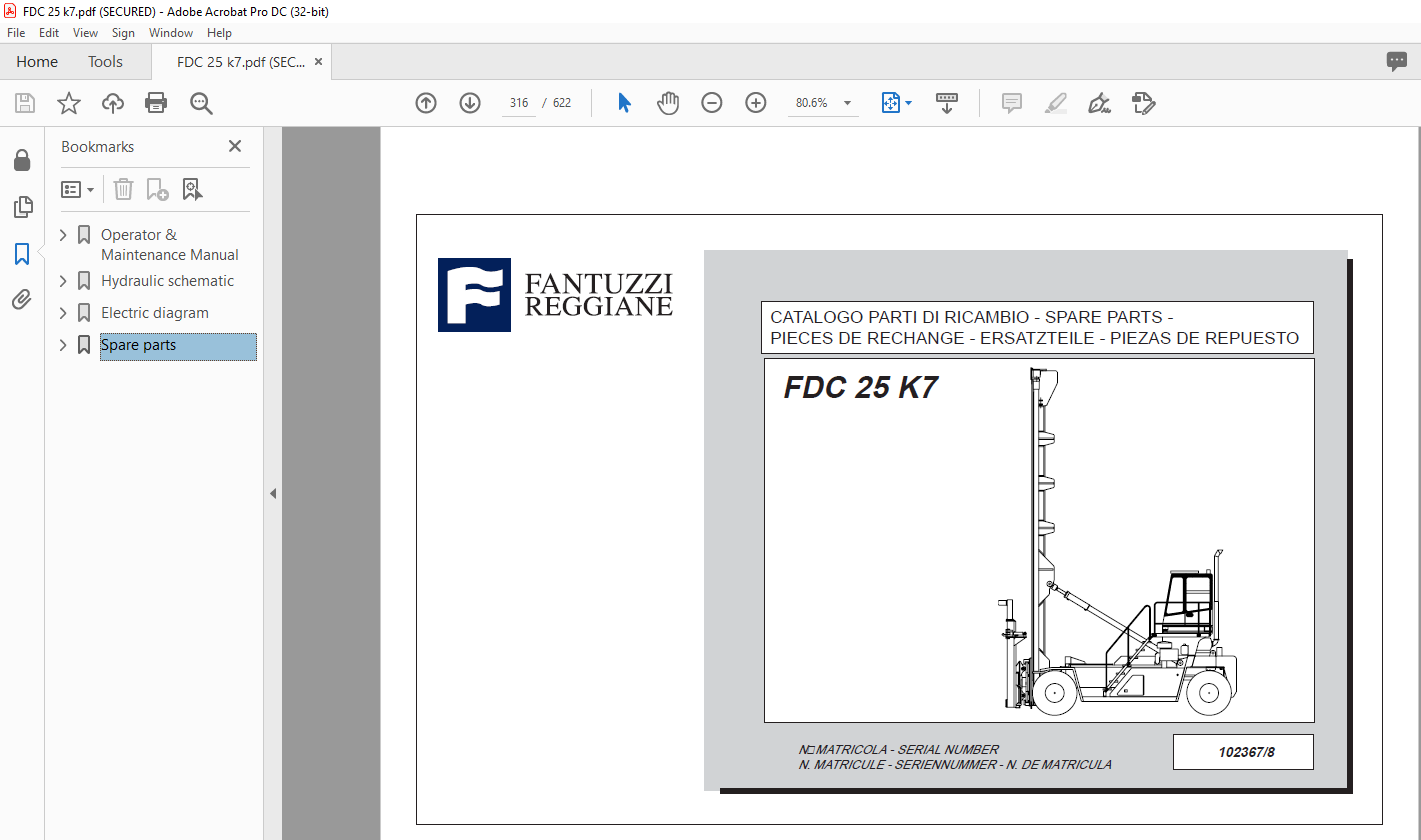
Fantuzzi Reggiane Forklift FDC 25 K7 Operator & Parts manual + Electrical & Hydraulic DiagramsManual
Fantuzzi Reggiane Forklift FDC 25 K7 Operator & Parts manual + Electrical & Hydraulic Diagrams Manual – PDF DOWNLOAD
FILE DETAILS:
Fantuzzi Reggiane Forklift FDC 25 K7 Operator & Parts manual + Electrical & Hydraulic Diagrams Manual – PDF DOWNLOAD
Language : English
Pages :622
Downloadable : Yes
File Type : PDF
TABLE OF CONTENTS:
Fantuzzi Reggiane Forklift FDC 25 K7 Operator & Parts manual + Electrical & Hydraulic Diagrams Manual – PDF DOWNLOAD
Operator & Maintenance Manual 1
Operator’s Manual 3
Index 5
Introduction 7
Foreword 7
Use of the manual 7
Symbols used in the manual 8
Sign plates 8
General information 9
General safety precautions 9
Instructions for truck operation and use 10
Warning notice 10
Personnel training 10
Operator’s responsabilities 11
Warranty 11
After-sales service 11
Dismantling and scrapping the truck 12
Product disposal 12
First aid 12
Section 1 – General information 13
General description & orientation 13
FDC 25 K 14
Technical specifications 15
Engine table 16
Important notice regarding braking 16
Section 2 – General safety 17
General Information 17
Local laws 17
Using common sense 17
Terminology 18
Safety responsibility of the operator 19
General operating guidelines for safe operation 20
Protection 23
Get on and get down 23
Electric line 24
Operating in wind 26
Scapping the machine 26
Section 3 – Grouncrew safety guidelines 27
Communication between operator and groundcrew 27
Recommended safety guidelines for groundcrew 28
Responsibilities of the groundcrew for safe operation 29
Section 4 – Operator’s controls 31
Introduction 31
Instrument layout in cab 32
Dashboard 33
Pedals 34
Brake pedal with switch 34
Instruments 35
Indicator lights 35
Upper beam headlight indicator 35
Blocked oil filter indicator 35
Low motor oil pressure indicator 35
Blocked air filter indicator 35
Battery recharge fault indicator 36
Parking brake indicator 36
Low transmission oil level indicator 36
Side light indicator 37
Direction indicators working indicator 37
Glow plug preheating indicator 37
Neutral gear engaged indicator 38
Twistlock light 38
Measuring instruments 39
Fuel level indicator 39
Control switches 40
Front windshield wiper and washer 40
Upper windshield wiper 40
Rear windshield wiper 40
Window Defrosters 40
Parking brake button 41
Emergency button 41
Work light switch 41
Spreader opening-closing button 41
Cab movement button 42
Engine revolution adjustment button 42
Ventilation system controls 43
Fan speed adjustment knob 43
Air conditioned button 43
Air conditioning/heating temperature regulation lever 43
Keys 44
Ignition Key 44
Gear change mode selection key 44
Safety bypass keys 44
Twistlock bypass key 45
Joystick controls 46
Mast luffing 48
Lift – Lower the spreader 48
Spreader translation and rotation and rotation controls 49
Gear selector 50
Direction indicator – Horn – Lights lever 51
seat adjustments 52
Motor control indicator lights 53
Fault Codes 54
Section 5 – Operating procedures 59
Introduction 59
Pre-operational inspection 61
Motor Oil Level 62
Motor coolant level 63
Hydraulic Oil Level 64
Transmission oil level 64
Leaks 65
Fuel tank 66
Tyres 67
Operator’s Cab 68
Operator’s Controls 68
Dry powder fire extinguisher 68
Structure 69
Lights 69
Warning Devices 70
Windshield Wipers 70
Welding 71
Engine start-up procedures 72
Normal start 73
Cold Weather Start 74
Using Booster Batteries or Starting Generators 75
Machine heating up procedure 77
Stopping the engine 78
Driving 79
Translations 80
General information 80
Speed 81
Operating on gradients 81
Steering 82
Load handling 83
Lifting unit controls 83
Doublebox Spreader – Refrigerated container handling 83
Picking up a container from a stack 84
Picking up a container from a stack (picture) 85
Depositing a Container on a Stack 86
Depositing a Container on a Stack (picture) 87
Picking up two containers from a stack 88
Picking up two containers from a stack (picture) 89
Depositing two Containers on a Stack 90
Depositing two Containers on a Stack (picture) 91
Parking procedures 92
Towing 93
Section 6 – Warranty 95
General Warranty Conditions 95
International Warranty 97
Introduction 97
Production Changes 97
Warranty Period 97
Test prior to delivery 98
Items covered by the warranty 99
Maintenance Manual101
Index103
Introduction105
Section 1 – General Information107
General information107
Personnel employed107
Inspection schedule107
General precaution concerning maintenance108
Check register109
Section 2 – Planned Maintenance121
How to refer to the maintenance instructions121
List of checks for maintenance122
General filling instructions128
Filling table FDC 100 – FDC 120129
Filling table FDC 150 – FDC 160 – FDC 180130
Filling table FDC 18 K – FDC 20 K131
Filling table FDC 25 K132
Filling table FDC 200133
Filling table FDC 240 – FDC 250134
Filling table FDC 280 – FDC 320 – FDC 350135
Filling rable FDC 380 – FDC 420 – FDC 450136
Filling table FDC 500137
Oil comparison table138
Section 3 – Structure139
Main frame139
Function139
Safety precautions139
Service139
Pins141
Function141
Safety precautions141
Service141
Section 4 – Diesel Engine143
Diesel motor143
Radiator144
Funtion144
Safety precaution144
Service144
Fume exhaust system145
Function145
Safety precautions145
Service145
Fuel system146
Function146
Safety precaution146
Service146
Section 5 – Transmission147
Transmission147
Function147
Safety precautions147
Service147
Automatic transmission148
Function148
Automatic mode148
Manual mode149
Safety functions149
Connection149
Section 6 – Drive Axle153
Differential axle153
Function153
Safety precautions154
Service155
Cardan shaft156
Function156
Safety precautions156
Service156
Section 7 – Steering axle157
Steering axle157
Function157
Safety precautions157
Service158
Axle structure159
Section 8 – Wheels161
Wheels161
Function161
Safety precautions161
Service162
Wheel and tyre fitting164
Materials required164
First stage164
Second Stage165
Third stage165
Fourth Stage166
Fifth Stage167
Periodical maintenance168
Procedure168
Tyre removal169
Removal procedure169
Rims170
Maintenance170
Checking the rims171
Section 9 – Hoist173
Description173
fig1173
fig2174
fig3175
Thrust shoes176
Function176
Service176
Lifting chain177
Function177
Precautions178
Servicing178
Hoisting chains – Inspection of wear179
Type of chain mounted on the truck179
Periodic inspection points180
Lubrication181
Cleaning the chain182
Lubricating the chain182
Adjusting the chain182
Checking for wear183
1 Fork dimensional checks183
2 Fork inclination check184
3 Fork shape checks185
4 Fork straightness check:186
5 Recommended non-destructive checks:187
Section 10 – Equipment189
Spreader189
Function189
Tecnical specifications190
Spreader type190
Dimensions190
Operations190
Side-shift190
Pile sloping190
Electrical System191
Hydraulic System191
Lifting capacity191
Weight191
Surface treatment191
Maintenance195
Section 11 – Hydraulic system199
Hydraulic system199
Safety precautions199
Hydraulic fluid sump200
Function200
Safety precautions200
Service200
Pumps202
Function202
Safety precautions202
Service203
Considerations203
Motors204
Function204
Service204
Hydraulic cylinders205
Function205
Safety precautions205
Service205
Hydraulic accumulators206
Function206
Safety precautions206
Service206
Fluid cooling circuit207
Function207
Safety precautions207
Service207
Distributors208
Function208
Safety precautions208
Service208
Section 12 – Electrical System209
Batteries209
Function209
Safety precautions209
Service209
Limit switch210
Function210
Safety precautions210
Service210
Electrical controls211
Function211
Safety precautions211
Service211
Section 13 – Air Conditioning System213
Refrigeration cycle diagram213
Heating system – conditioner214
Heating evaporator unit215
Compressor216
Evaporator217
Condenser218
Filter219
Filter head220
Pressure switch trinary221
Expansion valve222
Thermostat223
Test check224
Diagnosis of A/C system failure225
System malfuction226
The system doesn’t cool226
The system undercool227
Section 14 – Painting229
Paint229
Function229
Safety warnings229
Service229
Section 15 – Troubleshooting231
Troubleshooting231
Function231
Safety precautions231
Fault diagnosis232
Diesel engine232
Hydraulic motors235
Pumps238
Maximum pressure valve242
Check valve243
Direction adjustment valves243
Pressure adjustment valve244
Filters245
Pressure gauges245
Gearbox and torque converter246
Steering250
Overload control system251
Braking system252
Inching254
Section 16 – Technical Data255
Torque wrench setting255
Conversion chart and formulas256
Section 17 – Graphic Symbols259
Hydraulic Graphic Symbols259
Electrical Graphich Symbols275
Section 18 – Schematics281
Hydraulic schematic283
Components list284
Hydraulic schematic285
Brake system schematic286
Spreader side287
Electric diagram288
Legenda289
Color code289
The component of electric system290
Plug and junction box list291
Components list292
Wiring diagram296
General layout307
Dashboard layout308
Steering column309
Left panel311
Right panel312
Joystick column313
Cabin uses315
Spare parts316
Consulting the catalogue319
Information to be given with orders323
Spare parts purchasing and order confirmation form326
Subgroups number index328
Index347
Groups index376
IMAGES PREVIEW OF THE MANUAL:
More products