$34
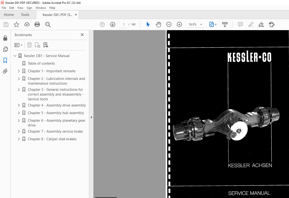
Fantuzzi Reggiane KESSLER ACHSEN 81 NLB SERVICE MANUAL – PDF DOWNLOAD
Fantuzzi Reggiane KESSLER ACHSEN 81 NLB SERVICE MANUAL – PDF DOWNLOAD
FILE DETAILS:
Fantuzzi Reggiane KESSLER ACHSEN 81 NLB SERVICE MANUAL – PDF DOWNLOAD
Language : English
Pages :148
Downloadable : Yes
File Type : PDF
TABLE OF CONTENTS:
Fantuzzi Reggiane KESSLER ACHSEN 81 NLB SERVICE MANUAL – PDF DOWNLOAD
Kessler D81 – Service Manual 1
Table of contents 3
Chapter 1 – Important remarks 4
11 – Important remarks 5
12 – Operation of creep gear, axle disconnection, inter axle diff-lock and cross diff-lock 7
13 – Instructions for ordering spare parts 9
Chapter 2 – Lubrication intervals and maintenance instructions 11
21 – General lubrication instructions 12
221 – Lubrication points 14
222 – Lubrication points 15
23 – Lubricants and lubrication intervals 16
231 – Recomendable hypoid gear oils corresp 18
24 – General maintenance instructions 19
Chapter 3 – General instructions for correct assembly and disassembly – Service tools 21
31 – General instructions for corrrect assembly and disassembly 22
321 – Using of Loctite and operating supplies 24
321 – Remarks for working up Loctite and operating supplies 24
322 – Utilization of Loctite and operating supplies 26
323 – Utilization of Loctite and operating supplies 27
33 – Tightening torques 28
34 – Tightening torques of wheel nuts 29
35 – Tightening torques for castle nuts on ball joints for track rods and ram cylinders 30
35 – Tightening torque of the adjusting nut resp slotted nut at flanges resp gearwheels ect 30
361 – Service tools 31
362 – Service tools 32
366 – Service tools 33
Chapter 4 – Assembly drive assembly 34
401 – Adjustment of gear meshing of Gleason gearrs 35
402 – Securing of the striking nut 37
41 – Drive assembly D51 39
411 – Adjustment of gear meshing 40
412 – Assembly of drive pinion bearing 42
413 – Assembly of the differential 44
414 – Assembly of drive assembly 46
416 – Assembly of the cross differential lock D51/D108/D71 through drive 48
43 – Drive assembly D71 50
431 – Assembly of the drive pinion bearing 51
432 – Assembly of the drive pinion bearing 53
433 – Adjustment of gear meshing 55
413 – Assembly of the differential 57
414 – Assembly of drive assembly 59
Chapter 5 – Assembly hub assembly 61
516 – Assembly of the spacer ring 62
53 – Hub assembly drive axle 63
531 – Assembly of the drive assembly onto the axle housing 64
532 – Assembly hub assembly 66
552 – Prepare wheel hub 67
552 – Mount wheel hub 67
571 – Adjustment of wheel bearings 69
572 – Wheel safety nut 70
581 – Assembly of the face seal 71
582 – Assembly of the face seal 73
583 – Assembly of the face seal 75
584 – Assembly of the face seal 77
Chapter 6 – Assembly planetary gear drive 79
62 – Planetary gear drive 80
611 – Prepare the ring gear and the ring gear carrier 81
611 – Assembly of the ring gear carrier 81
611 – Assembly of the thrust ring 81
611 – Assembly of the sun gear 81
612 – Assembly of planetary gear 83
621 – Assembly of planetary housing 85
621 – Adjustments of the axial clearance 85
614 – Disassembly of planetary gear 87
66 – Planetary gear drive 89
651 – Prepare the ring gear and the ring gear carrier 90
651 – Assembly of the ring gear carrier 90
651 – Assembly of the thrust ring 90
651 – Assembly of the sun gear 90
612 – Assembly of planetary gear 92
661 – Adjustment if the axial clearance 94
661 – Assembly of the planetary housing 94
614 – Disassembly of the planetary gear 96
Chapter 7 – Assembly service brake 98
701 – Instruction for the servicing and repair of hydraulic and mechanically actuated drum and disk brakes 99
711 – Assembly of the wet disk brake101
712 – Assembly of the piston seals102
712 – Assembly of o-ring and supporting ring102
712 – Assembly of the Omegat seal kit102
713 – Assembly of the piston104
714 – Prepare housing and chack the air gap106
715 – Air gap and wear dimension108
716 – Finish assembly109
717 – Tightness checking instruction for brake hydraulic system and cooling oil room111
718 – Remarks to the Wet Disk Brake113
719 – Remarks to the Wet Disk Brake115
737 – Brake disk117
Chapter 8 – Caliper diak brakes118
811 – Torque capability based on disk diameter and clamping stroke s119
812 – Contents120
813 – Description of the spring applied hydraulically released floating caliper disk brake122
814 – Description of the spring applied hydraulically released floating caliper disk brake124
815 – Picture 1: Cutaway view126
816 – Assembly instruction for the disk brake127
817 – Picture 5 – Picture 6129
818 – Picture 7 – Picture 8131
819 – Picture 9 – 91 – 92133
8110 – Picture 10 – Picture 11135
8111 – Picture 12 – Picture 13137
8112 – Picture 14 – Picture 15139
8113 – Picture 16 – Picture 17142
8114 – Picture 18 – Picture 19143
8115 – Service and maintenance145
8116 – Service and maintenance147
IMAGES PREVIEW OF THE MANUAL:
More products