$42
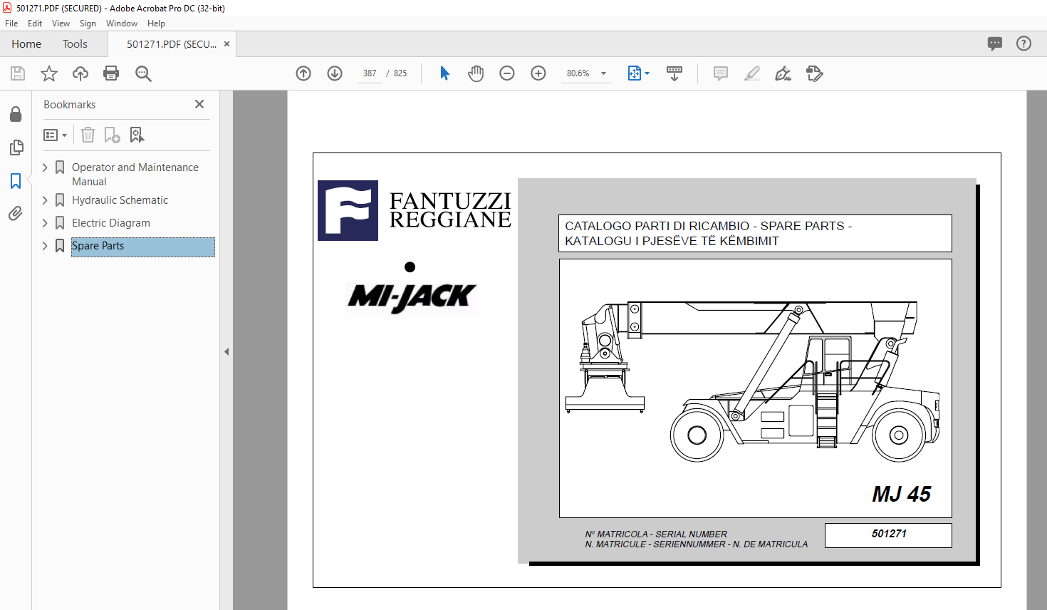
Fantuzzi Reggiane MI-Jack MJ 45 Operator & Parts manual + Electrical & Hydraulic Diagrams Manual
Fantuzzi Reggiane MI-Jack MJ 45 Operator & Parts manual + Electrical & Hydraulic Diagrams Manual – PDFDOWNLOAD
FILE DETAILS:’
Fantuzzi Reggiane MI-Jack MJ 45 Operator & Parts manual + Electrical & Hydraulic Diagrams Manual – PDFDOWNLOAD
Language : English
Pages :825
Downloadable : Yes
File Type : PDF
TABLE OF CONTENTS:
Fantuzzi Reggiane MI-Jack MJ 45 Operator & Parts manual + Electrical & Hydraulic Diagrams Manual – PDFDOWNLOAD
Operator and Maintenance Manual 1
Operator’s Manual 3
Index 5
Foreword 7
Use of the manual 7
Symbols used in the manual 8
Sign plates 8
General information 9
Instructions for truck operation and use 10
Warning notices 10
Personnel training 10
Operator’s responsibilities 11
Warranty 11
After-sales service 11
Dismantling and scrapping the truck 12
Product disposal 12
First aid 12
Net capacities under spreader 13
Section 1 – General Information 15
General description and positioning 15
Dimensions 16
CS 75 S5 – S6 – S7 16
CS 42 – 45 KC 18
CS 42 – 45 KM 20
CS 45 KL – KS 22
RS 50 24
RS 55 25
Technical specifications 17
CS 75 S5 – S6 – S7 17
CS 42 – 45 KC 19
CS 42 – 45 KM 21
CS 45 KL – KS 23
RS 50 – 55 26
Lifting capacity of the CS featuring piggy-back spreader 27
Motor table 28
Important notice regarding braking 29
Section 2 – General safety 31
General information 31
Local laws 31
Using common sense 31
Terminology 32
Safety responsibility of the operator 33
General operating guidelines for safe operation 34
Protection 37
Get on and get down 37
Electric line 38
Operating in wind 40
Scapping the machine 40
Section 3 – Safety guidelines 41
Communication between operator and groundcrew 41
Recommended safety guidelines for groundcrew 42
Responsibilities of the groundcrew for safe operation 43
Section 4 – Operator’s controls 45
Instrument layout 46
CS 75 – KM 46
CS KL – KS – RS 48
Dashboard 47
CS 75 – KM 47
CS KL – KS – RS 49
Pedals 50
Brake pedal with switch 50
Instruments 51
Indicator lights 51
Upper beam headlight indicator 51
Blocked oil filter indicator 51
Low motor oil pressure indicator 51
Blocked air filter indicator 51
Battery recharge fault indicator 52
Parking brake indicator 52
Low transmission oil level indicator 52
Low brake oil pressure indicator 52
Side light indicator 53
Direction indicators working indicator 53
Glow plug preheating indicator 53
Stabiliser-outriggers raised indicator 53
Stabilisers-outriggers lowered indicator 53
Neutral gear engaged indicator 54
Twistlock light 54
Low differential oil pressure indicator 54
Fault indicator in lubrication system 54
Measuring instruments 55
Hour counter 55
Transmission oil thermometer 55
Fuel level indicator 55
Battery voltmeter 56
Revolution counter 56
Engine coolant thermometer 56
Controls switches 57
Front windshield wiper and washer 57
Upper windshield wiper 57
Rear windshield wiper 57
Window Defrosters 57
Parking brake button 58
Emergency button 58
Work light switch 58
Spreader opening-closing button 59
30′ lock/unlock button (optional) 59
Moving cab movement button (optional) 60
Damping movement button (optional) 60
Grease pump button 61
Protection device 62
Elcos protection device 62
Elcos bypass key 62
Ventilation system controls 63
Heating adjustment knob 63
Air Conditioning adjustment knob 63
Fan speed adjustment knob 63
Air distribution knob 63
Keys 64
Ignition key 64
Senza nome 64
Auxiliary emergency pump ignition key (optional) 64
Gear change mode selection key 64
Key for opening/closing spreader with twistlocks secured (optional) 64
Safety by-pass keys 65
Function 65
Lifting by-pass key 65
Drop-stop by-pass key 66
Leg opening by-pass key 66
Twistlock by-pass key 66
Power cabinet 67
CS 75 – KM 67
CS KL – KS – RS 68
Gear selector 69
Direction indicator – horn – light lever 70
Joystick control 71
Telescopic arm movements 72
Twistlock rotation controls 72
Spreader translation and rotation controls 73
Spreader side-sloping function 74
Spreader piggy-back function 74
Front leg up/down button 74
Rear leg up/down button 74
Leg opening and closing button 74
Seat adjustments 75
Section 5 – Operating procedures 77
Introduction 77
Pre-operational inspection 79
Motor Oil Level 80
Motor coolant level 81
Hydraulic Oil Level 82
Transmission oil level 82
Leaks 83
Fuel tank 84
Tyres 85
Operator’s Cab 86
Operator ’s Controls 86
Dry powder fire extinguisher 86
Structure 87
Lights 87
Warning Devices 88
Windshield Wipers 88
Welding 89
Engine start-up procedures 90
Normal start 91
Cold Weather Start 92
Using Booster Batteries or Starting Generators 93
Machine heating up procedure 95
Stopping the engine 96
Driving 97
Traslazioni 98
General information 98
Speed 99
Operating on gradients 99
Steering100
Load handling101
Lifting unit controls101
Picking up a stacked container102
Procedure for picking up a stacked container103
Stacking a container Stacking a container104
Container stacking procedure Container stacking procedure105
Parking procedures106
Towing107
Section 6 – Warranty109
General warranty conditions109
International warranty111
Introduction111
Production changes111
Warranty period111
Test prior to delivery112
Items covered by the warranty113
Maintenance Manual115
Index117
Introduction119
Section 1 – General Information121
General Information121
Personnel employed121
Inspection schedule121
General precautions concerning maintenance122
Check register123
Reading the symbols in the manual124
System maintenance125
Introduction125
Preventive maintenance125
Inspection125
Restoration125
Programming maintenance125
Hidraulic systems125
Inspections126
Maintenance127
Repairs129
Eliminating faults130
Repair of hydraulic components131
Electrical systems131
Inspections131
Maintenance and repair132
Section 2 – Planned Maintenance135
How to refer to the maintenance instructions135
List of checks for maintenance136
Machine structure136
Diesel engine system136
Transmission137
Differential axle137
Cardan shafts137
Steering axle138
Wheels138
Telescopic arm138
Spreader SRP45139
Hydraulic system140
Electrical system141
Miscellaneous141
General filling instructions142
Filling table143
CS 75143
CS KC – KM144
CS KL – KS – RS145
Oil comparison table146
Section 3 – Structure147
Main frame147
Function147
Safety precautions147
Service147
Pins149
Function149
Safety precautions149
Service149
Section 4 – Diesel Engine151
Diesel Motor151
Radiator152
Function152
Safety precautions152
Service152
Fume exhaust system153
Function153
Safety precautions153
Service153
Fuel system154
Function154
Safety precautions154
Service154
Section 5 – Transmission155
Transmission155
Function155
Safety precautions155
Service155
Automatic transmission156
Function156
Automatic mode156
Manual mode157
Safety functions157
Section 6 – Drive Axle161
Drive axle161
Function161
Safety precautions162
Service163
Cardan shafts164
Function164
Safety precautions164
Service164
Section 7 – Steering Axle165
Steering axle165
Function165
Safety precautions165
Service166
Axle structure167
Section 8 – Wheels169
Wheels169
Function169
Safety precautions169
Service170
Wheel and tyre fitting172
Materials required172
First stage172
Second Stage173
Third stage173
Fourth Stage174
Fifth Stage175
Periodic maintenance176
Procedure176
Tyre removal177
Removal procedure177
Rims178
Maintenance178
Checking the rims179
Section 9 – Boom181
Telescopic arm181
Function181
Safety precautions182
Service182
Section 10 – Equipment187
SRP2 – 45187
Function187
Technical specifications191
Greasing points199
SRP2 – 45 TL188
Function188
Technical specifications193
Greasing points200
SRP2 – 55 TL189
Function189
Technical specifications195
Greasing points201
Safety precautions190
Procedure for replacing twistlocks197
Maintenance198
Rotation reduction gears202
Section 11 – Hydraulic System203
Hydraulic System203
Safety precautions203
Hydraulic fluid sump204
Function204
Safety precautions204
Service204
Pumps206
Function206
Safety precautions206
Service207
Considerations207
Motors208
Function208
Service208
Hydraulic cylinders209
Function209
Safety precautions209
Service209
Hydraulic accumulators210
Function210
Safety precautions210
Service210
Fluid cooling circuit211
Function211
Safety precautions211
Service211
Distributors212
Function212
Safety precautions212
Service212
Section 12 – Electrical System213
Batteries213
Function213
Safety precautions213
Service213
Limit switch214
Function214
Safety precautions214
Service214
Electrical controls215
Function215
Safety precautions215
Service215
Section 13 – Air Conditioning System217
Refrigeration cycle diagram217
Heating system – conditioner218
Heating evaporator unit219
Compressor220
Evaporator221
Condenser222
Filter223
Filter head224
Pressure switch trinary225
Expansion valve226
Thermostat227
Test check228
Diagnosis of A/C system failure229
System malfunction230
The system doesn’t cool230
The compressor fails to prime230
Formation of frost outside the coolant filter and expansion valve230
The system undercool231
The system does not cool down enough231
Low air flow at evaporator outlet231
The system does not cool down enough231
The system cools down intermittently due to internal frosting232
Section 14 – Painting233
Paint233
Function233
Safety warnings233
Service233
Section 15 – Troubleshooting235
Troubleshooting235
Function235
Safety precautions235
Fault diagnosis236
Diesel engine236
Hydraulic motors239
Pumps242
Maximum pressure valve246
Check valve247
Direction adjustment valves247
Pressure adjustment valve248
Filters249
Pressure gauges249
Gearbox and torque converter250
Steering254
Overload control system255
Braking system256
Inching258
Section 16 – Technical Data260
Torque wrench setting259
Conversion charts and formulas260
Section 17 – Graphic Symbols263
Hydraulic Graphic Symbols263
Electrical Graphic Symbols279
Section 18 – Schematics285
Hydraulic Schematic287
Components list288
Hydraulic schematic289
Brake system schematic290
Spreader291
Electric Diagram293
Section A294
Index295
Legenda296
Section B300
Electric Diagram301
Components list319
General layout336
Powertronic plug337
Engine/Gearbox signal 24 pole plug338
Spreader 24 pole plug339
Boom 24 pole plug340
Damping cells 16 pole plug340
Section C341
Electric box layout342
Power electric box343
Logic electric box348
Joystick board350
Terminal blocks layout353
Section D354
Dashboard layout355
Steering column357
Left panel359
Right panel360
Joystick column361
Cabin uses363
Dead man device364
Antitipping device input plug365
Antitipping device output plug366
Cabin367
Spreader371
General layout372
Main electric box376
Electric box on rotator377
Lh/Rh side electric box378
Spreader board379
Index427
Groups index467
IMAGES PREVIEW OF THE MANUAL:
More products