$42
Fantuzzi Reggiane MI-Jack RS 55 Operator & Parts manual + Electrical & Hydraulic Diagrams Manual –
Fantuzzi Reggiane MI-Jack RS 55 Operator & Parts manual + Electrical & Hydraulic Diagrams Manual – PDF DOWNLOAD
FILE DETAILS:
Fantuzzi Reggiane MI-Jack RS 55 Operator & Parts manual + Electrical & Hydraulic Diagrams Manual – PDF DOWNLOAD
Language : English
Pages :788
Downloadable : Yes
File Type : PDF
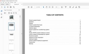
TABLE OF CONTENTS:
Fantuzzi Reggiane MI-Jack RS 55 Operator & Parts manual + Electrical & Hydraulic Diagrams Manual – PDF DOWNLOAD
Operator & Maintenance Manual 1
Operator’s Manual 3
Index 5
Introduction 7
Foreword 7
Use of the manual 7
Symbols used in the manual 8
Sign plates 8
General Information 9
General safety precautions 9
Instructions for truck operation and use 10
Warning notices 10
Personnel training 10
Operator’s responsibilities 11
Warranty 11
After-sales service 11
Dismantling and scrapping the truck 12
Product disposal 12
First aid 12
Section 1 – General Information 13
General description and positioning 13
Dimensions CS 45 KL – KS 0
Technical specifications CS 45 KL – KS 0
Only for machine having movable cab 16
Motor table 17
Important notice regarding braking 18
Section 2 – General safety 19
General Information 19
Local laws 19
Using common sense 19
Terminology 20
Safety responsibility of the operator 21
General operating guidelines for safe operation 22
Protection 25
Get on and get down 25
Electric line 26
Operating in wind 28
Scapping the machine 28
Section 3 – Safety guidelines 29
Communication between operator and groundcrew 29
Recommended safety guidelines for groundcrew 30
Responsibilities of the groundcrew for safe operation 31
Section 4 – Operator’s controls 33
Introduction 33
Instrument layout in cab 34
Dashboard 35
Pedals 36
Brake pedal with switch 36
Control switches 37
Parking brake button 37
Emergency stop button 37
Twistlock light 37
Spreader opening-closing button 38
30′ lock/unlock button (optional) 38
Digicontrol’s keyboard 39
Ventilation system controls 40
Fan speed adjustment knob 40
Air conditioned button 40
Air conditioning/heating temperature regulation lever 40
Keys 41
Ignition key 41
Gear change mode selection key 41
Twistlock by-pass key 41
Key for opening/closing spreader with twistlocks secured (optional) 41
Gear selector 42
Direction indicator – Horn 43
Joystick controls 44
Telescopic arm movements 45
Twistlock rotation controls 45
Spreader translation and rotation controls 46
Seat adjustments 47
Section 5 – Operating procedures 49
Introduction 49
Pre-operational inspection 51
Motor Oil Level 52
Motor coolant level 53
Hydraulic Oil Level 54
Transmission oil level 54
Leaks 55
Fuel tank 56
Tyres 57
Operator’s Cab 58
Operator ’s Controls 58
Dry powder fire extinguisher (optional) 58
Structure 59
Lights 59
Warning Devices 60
Windshield Wipers 60
Welding 61
Engine start-up procedures 62
Normal Start 63
Cold Weather Start 64
Using Booster Batteries or Starting Generators 65
Machine heating up procedure 67
Stopping the engine 68
Driving 69
Traslazioni 70
General information 70
Speed 71
Operating on gradients (slopes) 71
Steering 72
Load Handling 73
Lifting unit controls 73
Picking up a stacked container 74
Procedure for picking up a stacked container 75
Stacking a container 76
Container stacking procedure 77
Parking procedures 78
Towing 79
Section 6 – Warranty 81
General Warranty Conditions 81
International Warranty 83
Introduction 83
Production Changes 83
Warranty Period 83
Test prior to delivery 84
Items covered by the warranty 85
Maintenance Manual 87
Index 89
Introduction 91
Section 1 – General Information 93
General information 93
Personnel employed 93
Inspection schedule 93
General precaution concerning maintenance 94
Check register 95
Section 2 – Planned Maintenance105
How to refer to the maintenance instructions105
List of checks for maintenance106
General filling instructions112
Filling table113
CS 75113
CS KC – KM114
CS KL – KS – RS 50 – RS 55115
Oil comparison table116
Section 3 – Structure117
Main frame117
Function117
Safety precautions117
Service117
Pins119
Function119
Safety precautions119
Service119
Section 4 – Diesel Engine121
Diesel motor121
Radiator122
Funtion122
Safety precaution122
Service122
Fume exhaust system123
Function123
Safety precautions123
Service123
Fuel system124
Function124
Safety precaution124
Service124
Section 5 – Transmission125
Transmission125
Function125
Safety precautions125
Service125
Automatic transmission126
Function126
Automatic mode126
Manual mode127
Safety functions127
Connection127
Section 6 – Drive axle131
Differential axle131
Function131
Safety precautions132
Service133
Cardan shafts134
Function134
Safety precautions134
Service134
Section 7 – Steering axle135
Steering axle135
Function135
Safety precautions135
Service136
Axle structure137
Section 8 – Wheels139
Wheels139
Function139
Safety precautions139
Service140
Wheel and tyre fitting142
Materials required142
First stage142
Second Stage143
Third stage143
Fourth Stage144
Fifth Stage145
Periodical maintenance146
Procedure146
Tyre removal147
Removal procedure147
Rims148
Maintenance148
Checking the rims149
Section 9 – Boom151
Telescopic Arm151
Function151
Safety precaution152
Service152
Section 10 – Equipment157
Spreader SRP2-45157
Function157
Technical specifications161
Greasing points169
Spreader SRP2-45TL158
Function158
Technical specifications163
Greasing points170
Spreader SRP2-55TL159
Function159
Safety precautions160
Technical specifications165
Greasing points171
Procedure for replacing twistlocks167
Maintenance168
Rotation reduction gears172
Spreader fixing points for lifting173
Section 11 – Hydraulic system175
Hydraulic system175
Safety precautions175
Hydraulic fluid sump176
Function176
Safety precautions176
Service176
Pumps178
Function178
Safety precautions178
Service179
Considerations179
Motors180
Function180
Service180
Hydraulic cylinders181
Function181
Safety precautions181
Service181
Hydraulic accumulators182
Function182
Safety precautions182
Service182
Fluid cooling circuit183
Function183
Safety precautions183
Service183
Distributors184
Function184
Safety precautions184
Service184
Section 12 – Electrical System185
Batteries185
Function185
Safety precautions185
Service185
Limit switch186
Function186
Safety precautions186
Service186
Electrical controls187
Function187
Safety precautions187
Service187
Section 13 – Air Conditioning System189
Refrigeration cycle diagram189
Heating system – conditioner190
Heating evaporator unit191
Compressor192
Evaporator193
Condenser194
Filter195
Filter head196
Pressure switch trinary197
Expansion valve198
Thermostat199
Test check200
Diagnosis of A/C system failure201
System malfuction202
The system doesn’t cool202
The system undercool203
Section 14 – Painting205
Paint205
Function205
Safety warnings205
Service205
Section 15 – Troubleshooting207
Troubleshooting207
Function207
Safety precautions207
Fault diagnosis208
Diesel engine208
Hydraulic motors211
Pumps214
Maximum pressure valve218
Check valve219
Direction adjustment valves219
Pressure adjustment valve220
Filters221
Pressure gauges221
Gearbox and torque converter222
Steering226
Overload control system227
Braking system228
Inching230
Section 16 – Technical Data231
Torque wrench setting231
Conversion chart and formulas232
Section 17 – Graphic Symbols235
Hydraulic Graphic Symbols235
Electrical Graphich Symbols251
Section 18 – Schematics257
Hydraulic System257
Electrical System257
Hydraulic schematic259
Components list260
Hydraulic schematic261
Brake system schematic262
Spreader263
Electric diagram264
Legenda265
Color code265
The components of electric system266
Plug and junction box list267
Components list268
Wiring diagram274
EB1 Can electric box300
EB2 Main electric box302
EB9 Heaters electric box303
EB5 Spreader main electric box304
EB6 Spreader elctric box305
Cable W1X307
Cable W2X310
Cable W3X315
Cable W5X318
Cable W6X321
Cable W7X323
Cable W8X324
Cable W9X325
Cable W10X325
PLC1 (Cabin)326
PLC2 (main elbox)327
PLC3 (spreader)328
PLC4 (spreader)329
Keyboard330
Multican D107-D108331
Spare parts332
Consulting the catalogue335
Information to be given with orders339
Spare parts purchasing and order confirmation form342
Sub groups number index344
Index373
Groups index414
IMAGES PREVIEW OF THE MANUAL:
More products