$39
Fantuzzi Reggiane MJ 7.5 S6 Operator & Parts manual + Electrical & Hydraulic Diagrams Manual – PDF
Fantuzzi Reggiane MJ 7.5 S6 Operator & Parts manual + Electrical & Hydraulic Diagrams Manual – PDF DOWNLOAD
FILE DETAILS:
Fantuzzi Reggiane MI – JACK MJ 7.5 S6 Operator & Parts manual + Electrical & Hydraulic Diagrams Manual – PDF DOWNLOAD
Language : English
Pages :727
Downloadable : Yes
File Type : PDF
TABLE OF CONTENTS:
Fantuzzi Reggiane MI – JACK MJ 7.5 S6 Operator & Parts manual + Electrical & Hydraulic Diagrams Manual – PDF DOWNLOAD
Operator and Maintenance Manual 1
Operator’s Manual 3
Index 5
Foreword 7
Use of the manual 7
Symbols used in the manual 8
Sign plates 8
General information 9
Instructions for truck operation and use 10
Warning notices 10
Personnel training 10
Operator’s responsibilities 11
Warranty 11
After-sales service 11
Dismantling and scrapping the truck 12
Product disposal 12
First aid 12
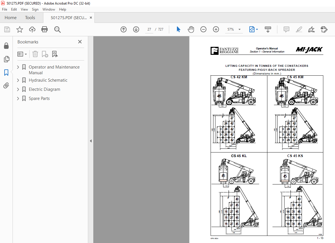
Net capacities under spreader 13
Section 1 – General Information 15
General description and positioning 15
Dimensions 16
Lifting capacity of the CS featuring piggy-back spreader 27
Motor table 28
Important notice regarding braking 29
Section 2 – General safety 31
General information 31
Local laws 31
Using common sense 31
Terminology 32
Safety responsibility of the operator 33
General operating guidelines for safe operation 34
Protection 37
Get on and get down 37
Electric line 38
Operating in wind 40
Scapping the machine 40
Section 3 – Safety guidelines 41
Communication between operator and groundcrew 41
Recommended safety guidelines for groundcrew 42
Responsibilities of the groundcrew for safe operation 43
Section 4 – Operator’s controls 45
Introduction 45
Instrument layout in cab 46
Dashboard 47
Brake pedal with switch 48
Indicator lights and instruments 49
Upper beam headlight indicator 49
Blocked oil filter indicator 49
Low motor oil pressure indicator 49
Blocked air filter indicator 49
Battery recharge fault indicator 50
Parking brake indicator 50
Low transmission oil level indicator 50
Side light indicator 51
Direction indicators working indicator 51
Glow plug preheating indicator 51
Neutral gear engaged indicator 51
Ignition key 52
Engine revolution adjustment button 52
Work light switch 52
Engine control indicator lights 53
Fault codes 54
Left dashboard 59
Hour counter 60
Stair light switch 60
Engine control indicator lights 60
Fan speed adjustment knob 61
Air conditioned button 61
Air conditioning/heating temperature regulation lever 61
Right dashboard 62
Low brake oil pressure indicator 62
Transmission oil thermometer 63
Fuel level indicator 63
Engine coolant thermometer 63
Joystick controls 64
Mast luffing 65
Lift – Lower the spreader 65
Spreader translation and rotation controls 66
Twistlock rotation controls 66
Spreader side-sloping function 67
Control dashboard 68
Twistlock light 68
Twistlock by-pass key 68
Gear change mode selection key 68
Front windshield wiper and washer 69
Upper windshield wiper 69
Rear windshield wiper 69
Window Defrosters 69
Parking brake button 70
Emergency button 70
Spreader opening-closing button 71
Keys 72
Auxiliary emergency pump ignition key (optional) 72
Key for opening/closing spreader with twistlocks secured (optional) 72
Safety by-pass keys 73
Lifting bypass key (in the electrical compartment) 73
Drop-stop bypass key (in electrical compartment) 74
Leg opening bypass key (in the electrical compartment and only for piggy-back spreader) 74
Power cabinet 75
Gear selector 76
Manual operation 76
Automatic operation 76
Direction indicator – Horn – Lights lever 77
Seat adjustments 78
Section 5 – Operating procedures 79
Introduction 79
Pre-operational inspection 81
Motor Oil Level 82
Motor coolant level 83
Hydraulic Oil Level 84
Transmission oil level 84
Leaks 85
Fuel tank 86
Tyres 87
Operator’s Cab 88
Operator ’s Controls 88
Dry powder fire extinguisher 88
Structure 89
Lights 89
Warning Devices 90
Windshield Wipers 90
Welding 91
Engine start-up procedures 92
Normal start 93
Cold Weather Start 94
Using Booster Batteries or Starting Generators 95
Machine heating up procedure 97
Stopping the engine 98
Driving 99
Traslazioni100
General information100
Speed101
Operating on gradients101
Steering102
Load handling103
Lifting unit controls103
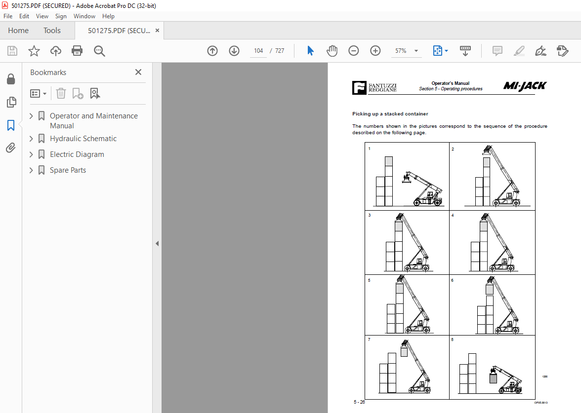
Picking up a stacked container104
Procedure for picking up a stacked container105
Stacking a container Stacking a container106
Container stacking procedure Container stacking procedure107
Parking procedures108
Towing109
Section 6 – Warranty111
General warranty conditions111
International warranty113
Introduction113
Production changes113
Warranty period113
Test prior to delivery114
Items covered by the warranty115
Maintenance Manual117
Index119
Introduction121
Section 1 – General Information123
General Information123
Personnel employed123
Inspection schedule123
General precautions concerning maintenance124
Check register125
Reading the symbols in the manual126
System maintenance127
Introduction127
Preventive maintenance127
Inspection127
Restoration127
Programming maintenance127
Hidraulic systems127
Inspections128
Maintenance129
Repairs131
Eliminating faults132
Repair of hydraulic components133
Electrical systems133
Inspections133
Maintenance and repair134
Section 2 – Planned Maintenance137
How to refer to the maintenance instructions137
List of checks for maintenance138
Machine structure138
Diesel engine system138
Transmission139
Differential axle139
Cardan shafts139
Steering axle140
Wheels140
Telescopic arm140
Spreader SRP45141
Hydraulic system142
Electrical system143
Miscellaneous143
General filling instructions144
Filling table145
CS 75145
CS KC – KM146
CS KL – KS – RS147
Oil comparison table148
Section 3 – Structure149
Main frame149
Function149
Safety precautions149
Service149
Pins151
Function151
Safety precautions151
Service151
Section 4 – Diesel Engine153
Diesel Motor153
Radiator154
Function154
Safety precautions154
Service154
Fume exhaust system155
Function155
Safety precautions155
Service155
Fuel system156
Function156
Safety precautions156
Service156
Section 5 – Transmission157
Transmission157
Function157
Safety precautions157
Service157
Automatic transmission158
Function158
Automatic mode158
Manual mode159
Safety functions159
Section 6 – Drive Axle163
Drive axle163
Function163
Safety precautions164
Service165
Cardan shafts166
Function166
Safety precautions166
Service166
Section 7 – Steering Axle167
Steering axle167
Function167
Safety precautions167
Service168
Axle structure169
Section 8 – Wheels171
Wheels171
Function171
Safety precautions171
Service172
Wheel and tyre fitting174
Materials required174
First stage174
Second Stage175
Third stage175
Fourth Stage176
Fifth Stage177
Periodic maintenance178
Procedure178
Tyre removal179
Removal procedure179
Rims180
Maintenance180
Checking the rims181
Section 9 – Boom183
Telescopic arm183
Function183
Safety precautions184
Service184
Section 10 – Equipment189
SRP2 – 45189
Function189
Technical specifications193
Greasing points201
SRP2 – 45 TL190
Function190
Technical specifications195
Greasing points202
SRP2 – 55 TL191
Function191
Technical specifications197
Greasing points203
Safety precautions192
Procedure for replacing twistlocks199
Maintenance200
Rotation reduction gears204
Section 11 – Hydraulic System205
Hydraulic System205
Safety precautions205
Hydraulic fluid sump206
Function206
Safety precautions206
Service206
Pumps208
Function208
Safety precautions208
Service209
Considerations209
Motors210
Function210
Service210
Hydraulic cylinders211
Function211
Safety precautions211
Service211
Hydraulic accumulators212
Function212
Safety precautions212
Service212
Fluid cooling circuit213
Function213
Safety precautions213
Service213
Distributors214
Function214
Safety precautions214
Service214
Section 12 – Electrical System215
Batteries215
Function215
Safety precautions215
Service215
Limit switch216
Function216
Safety precautions216
Service216
Electrical controls217
Function217
Safety precautions217
Service217
Section 13 – Air Conditioning System219
Refrigeration cycle diagram219
Heating system – conditioner220
Heating evaporator unit221
Compressor222
Evaporator223
Condenser224
Filter225
Filter head226
Pressure switch trinary227
Expansion valve228
Thermostat229
Test check230
Diagnosis of A/C system failure231
System malfunction232
The system doesn’t cool232
The compressor fails to prime232
Formation of frost outside the coolant filter and expansion valve232
The system undercool233
The system does not cool down enough233
Low air flow at evaporator outlet233
The system does not cool down enough233
The system cools down intermittently due to internal frosting234
Section 14 – Painting235
Paint235
Function235
Safety warnings235
Service235
Section 15 – Troubleshooting237
Troubleshooting237
Function237
Safety precautions237
Fault diagnosis238
Diesel engine238
Hydraulic motors241
Pumps244
Maximum pressure valve248
Check valve249
Direction adjustment valves249
Pressure adjustment valve250
Filters251
Pressure gauges251
Gearbox and torque converter252
Steering256
Overload control system257
Braking system258
Inching260
Section 16 – Technical Data262
Torque wrench setting261
Conversion charts and formulas262
Section 17 – Graphic Symbols265
Hydraulic Graphic Symbols265
Electrical Graphic Symbols281
Section 18 – Schematics287
Hydraulic Schematic289
Components list290
Hydraulic schematic291
Brake system schematic292
Spreader schematic293
Electric Diagram295
Legenda296
Plug and junction box list298
Components list299
Electric diagram304
General layout318
Dashboard layout319
Steering column320
Left panel322
Right panel323
Joystick column324
Cabin uses326
Electric box layout328
Electric box329
Scheda spreader – Joystick331
Joystick board332
Spreader334
Spare Parts349
Consulting the catalogue352
Information to be given whit orders356
Spare parts purchasing and order confirmation form359
Sub groups number index361
Analitic index385
Groups index417
IMAGES PREVIEW OF THE MANUAL:
More products