$22
Gehl 1287 Manure Spreader Parts Manual(907543B) – PDF DOWNLOAD
Gehl 1287 Manure Spreader Parts Manual(907543B) – PDF DOWNLOAD
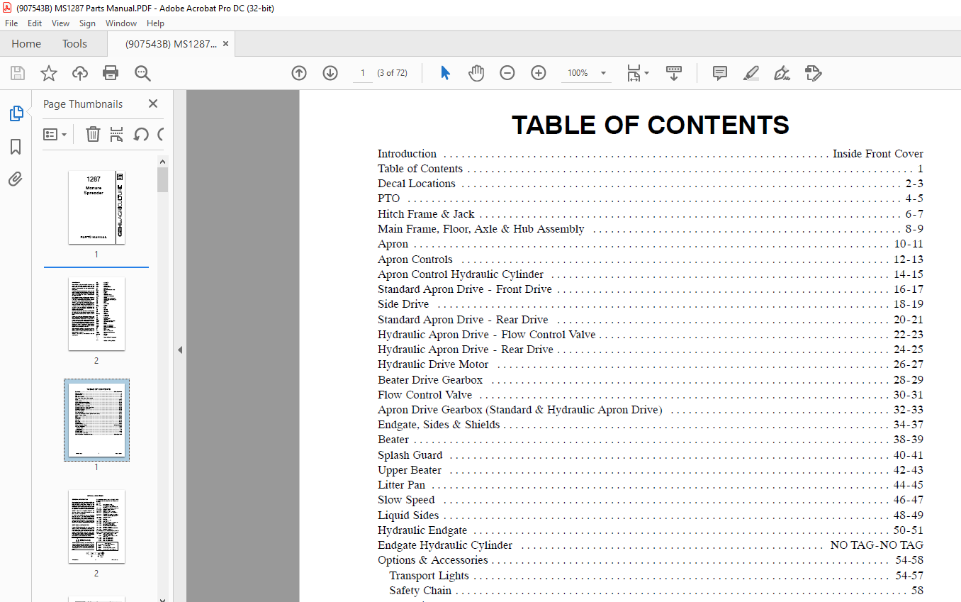
TABLE OF CONTENTS:
Gehl 1287 Manure Spreader Parts Manual(907543B) – PDF DOWNLOAD
Introduction Inside Front Cover
Table of Contents 1
Decal Locations 2-3
PTO 4-5
Hitch Frame & Jack 6-7
Main Frame, Floor, Axle & Hub Assembly 8-9
Apron 10-11
Apron Controls 12-13
Apron Control Hydraulic Cylinder 14-15
Standard Apron Drive – Front Drive 16-17
Side Drive 18-19
Standard Apron Drive – Rear Drive 20-21
Hydraulic Apron Drive – Flow Control Valve 22-23
Hydraulic Apron Drive – Rear Drive 24-25
Hydraulic Drive Motor 26-27
Beater Drive Gearbox 28-29
Flow Control Valve 30-31
Apron Drive Gearbox (Standard & Hydraulic Apron Drive) 32-33
Endgate, Sides & Shields 34-37
Beater 38-39
Splash Guard 40-41
Upper Beater 42-43
Litter Pan 44-45
Slow Speed 46-47
Liquid Sides 48-49
Hydraulic Endgate 50-51
Endgate Hydraulic Cylinder NO TAG-NO TAG
Options & Accessories 54-58
Transport Lights 54-57
Safety Chain 58
Alphabetical Index 59
Numerical Index 60-67
Hydraulic Fitting Torque Data 68
Standard Hardware Torque Specifications Inside Back Cover
DESCRIPTION:
Gehl 1287 Manure Spreader Parts Manual(907543B) – PDF DOWNLOAD
Introduction:
- When ordering service parts, please specify the correct part number, full description, quantity required, unit model number, and serial number. For your safety and continued proper operation, only use genuine GEHL service parts.
- The Manure Spreader model and serial numbers for this unit are located on a decal on the left side of the main frame at the front left corner of the box. Please note that “right” and “left” are determined from a position standing behind the Manure Spreader.
- GEHL Company reserves the right to make changes or improvements to the design or construction of any part of the unit without incurring the obligation to install such changes on any previously delivered units.
- NOTE: Company policy prohibits the sale of replacement tires for all GEHL machinery. However, replacement wheel sets are available, and tire size information is provided with the wheel sets to facilitate replacement tire selection. ALL REPLACEMENT TIRES MUST BE PURCHASED LOCALLY.
- Please refer to the abbreviations table located on this page for the various fastener descriptions. Standard attaching hardware torque values are provided on the inside back cover.
- In the exploded view parts list, Reference Numbers may have additional information following the Reference Number. A tear drop symbol indicates an application of a “wet” product such as oil, and the number inside the tear drop will correspond to the description in the Parts List. A number inside a hexagon will be the torque value required, in foot-pounds, on the associated Reference Number. Items shown in the parts list that do not have Reference Numbers are shown for reference purposes only and are NOT available for purchase.
- Unless otherwise specified, all cap screws or bolts are Grade 5, zinc-plated. Hexagon nuts for Grade 5 cap screws or bolts are Grade B, while hexagon nuts for other cap screws or bolts are Grade A.
GENERAL INFORMATION:
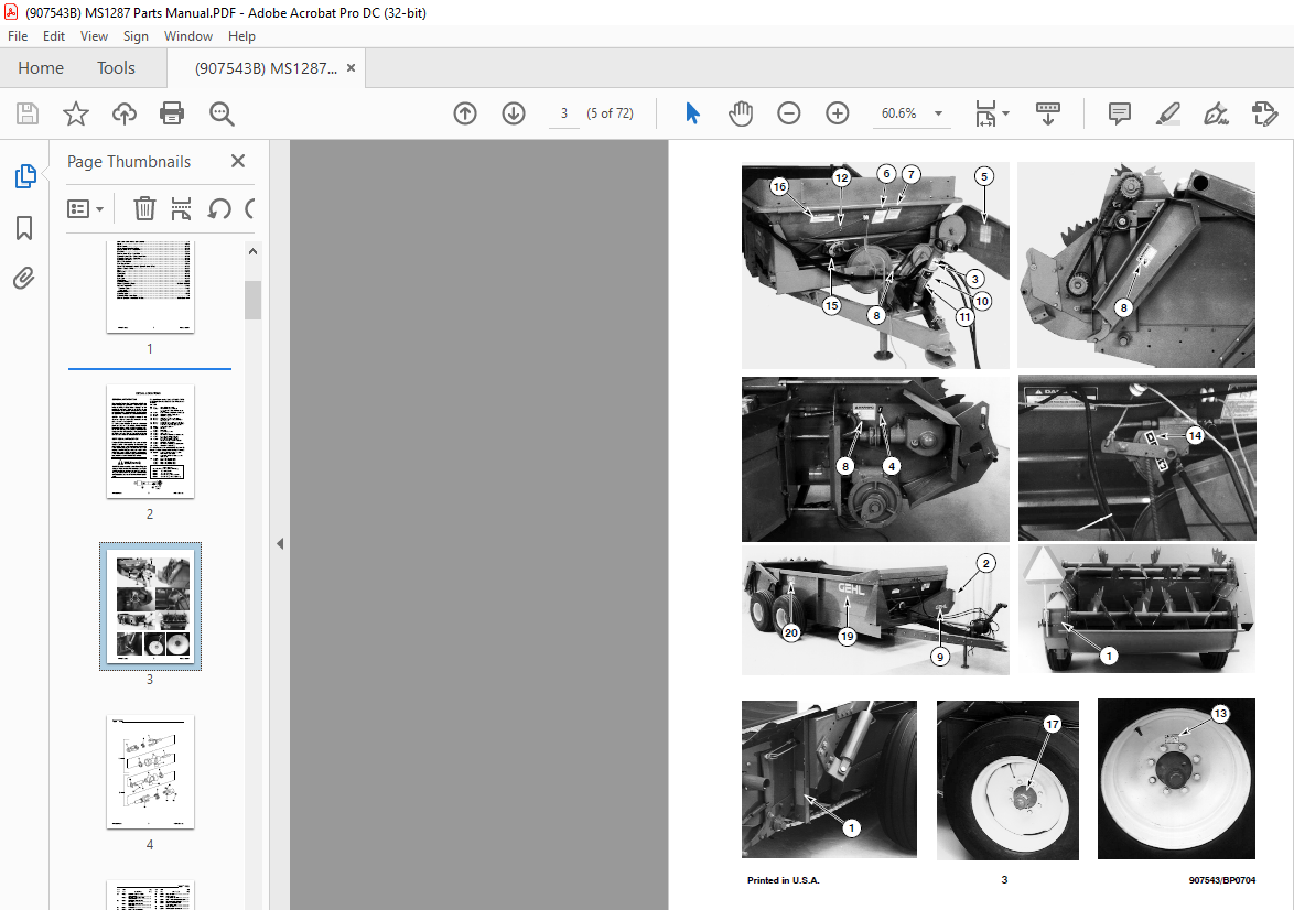
- Decal location information is provided to assist in the proper selection and application of new decals, in the event the original decals become damaged or the machine is repainted. Please refer to the listing for the illustration reference number, part number, description, and quantity of each decal provided in the kit. Refer to the appropriate illustrations for replacement locations.
- To ensure proper selection for correct replacement decals, compare all of the various close-up location illustrations of the machine BEFORE starting to refinish the unit. Then, circle each pictured decal applicable to your machine, while checking off its part number in the listing. After verifying all the decals needed for replacement, set aside any unneeded decals for disposal.
IMAGES PREVIEW OF THE MANUAL:
More products