$22
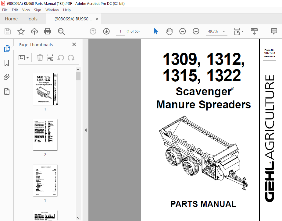
Gehl 1309, 1312, 1315, 1322 Scavenger Manure Spreaders Parts Manual(907503) – PDF DOWNLOAD
Gehl 1309, 1312, 1315, 1322 Scavenger Manure Spreaders Parts Manual(907503) – PDF DOWNLOAD
FILE DETAILS:
Gehl 1309, 1312, 1315, 1322 Scavenger Manure Spreaders Parts Manual(907503) – PDF DOWNLOAD
Language : English
Pages : 56
Downloadable : Yes
File Type : PDF
Size: 1.63 MB
TABLE OF CONTENTS:
Gehl 1309, 1312, 1315, 1322 Scavenger Manure Spreaders Parts Manual(907503) – PDF DOWNLOAD
Introduction Inside Front Cover
Decal Locations 2-3
Auger Liner Slides & Hitch 4-5
Auger Drive 6-7
Expeller & Discharge Gate 8-9
Input Shaft & Expeller Drive 10-11
Hydraulics 12-15
Guards & Shields 16-17
1309 – Single Axles 18
1312 – Single Axles 19
1312 – Tandem Axles 20-21
1315 – Tandem Axles 22-23
1322 – Tandem Axles 24-25
1322 – Tandem Axles (w/Brakes) 26-27
1322 – Tandem Axles (Brake Hydraulics) 28-29
Transport Lights 30-31
Tank Repair Panels 32
Component Breakdowns 33-39
Augers 33
Hydraulic Cylinders 34
Splash Guards & Rails 35
Hitchjacks 36-37
PTO – 540 RPM (1309 & 1312 1315) 38
PTO – 1000 RPM (1322) 39
Options & Accessories 40-43
Hydraulic Lid Kit 40-41
Safety Chains 42
Chain Oiler 43-44
Index 45
Numerical Index 46-51
Hydraulic Fitting Data 52
Standard Hardware Torque Specifications Inside Back Cover
DESCRIPTION:
Gehl 1309, 1312, 1315, 1322 Scavenger Manure Spreaders Parts Manual(907503) – PDF DOWNLOAD
- Introduction
- When ordering service parts, specify the correct part number, full description, quantity required, the unit model number and serial number.
- The Spreader model and serial numbers are on a plate located on the front, left corner of the tank. “Right” and “left” are determined from a position standing behind the Spreader and facing in the direction of travel.
- From this position, the expeller is on the “right” side. GEHL Company reserves the right to make changes or improvements in the design or construction of any part of the unit without incurring the obligation to install such changes on any previously delivered units.
GENERAL INFORMATION
- Decal locations information is provided to assist in the proper selection and application of new decals, in the event the original decals become damaged or the machine is repainted. Refer to the listing for the photograph reference number, part number, description and quantity of each decal provided in the kit. Refer to the appropriate photographs for replacement locations
- To ensure proper selection for correct replacement decals, compare all of the various close-up location photographs to your machine BEFORE starting to refinish the unit. Then circle each pictured decal (applicable to your machine) while checking off its part number in the listing. After you have verified all the decals needed for replacement, set aside unneeded decals for disposal.
IMAGES PREVIEW OF THE MANUAL:
More products