$23
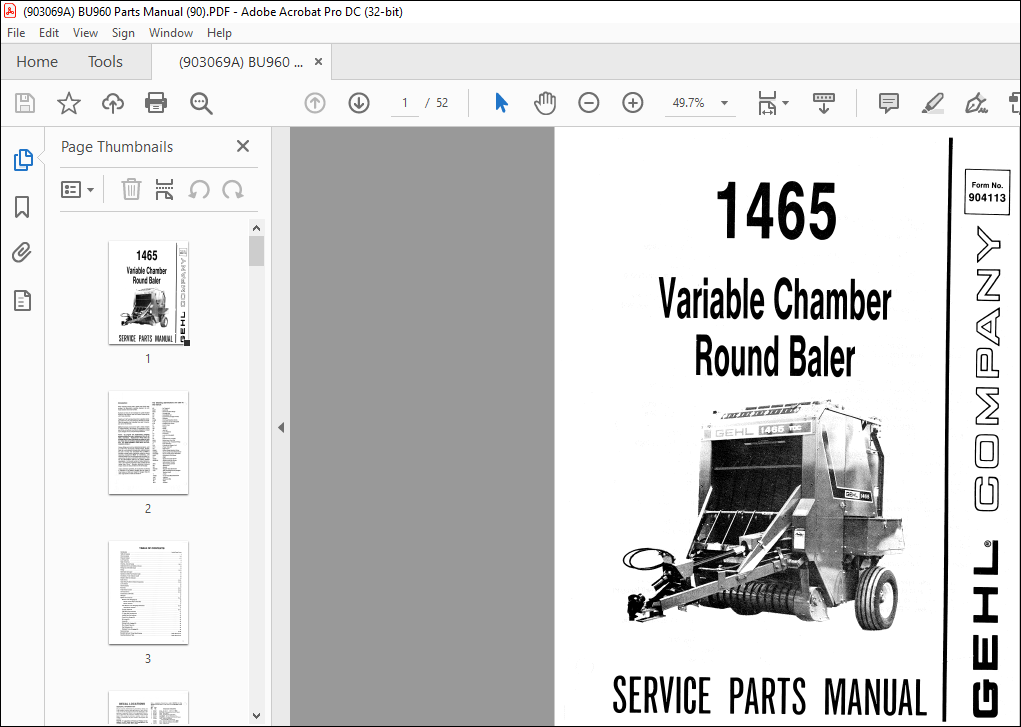
Gehl 1465 Variable Chamber Round Baler Service Parts Manual(904113) – PDF DOWNLOAD
Gehl 1465 Variable Chamber Round Baler Service Parts Manual(904113) – PDF DOWNLOAD
TABLE OF CONTENTS:
Gehl 1465 Variable Chamber Round Baler Service Parts Manual(904113) – PDF DOWNLOAD
Introduction Inside Front Cover
Table of Contents 1
Decai Locations 2-5
Frame & Fenders 6-7
I eft Twine Box 8
Right Twine Box 9
Drawbar, Axles & Ramps 10-11
Implement Drive Line Shields & Covers 12
Pickup Lift & Overfill Clutch 13
Pickup 14-15
Bale Starter & Scraper 16
Sprocket & Roller Part Number Guide 17
Crossframe, Twine Tubes & Cutoff 18
Shuttle & Bale Size lndicator 19
Roller Drives 20-21
Upper Belts, Rollers & Related Components 22-23
Lower Rollers 24
Gate Hydraulics 25
Rear Gate 26-27
Total Density Control 28-29
Universal Drives 30-32
Transmission (540 RPM) 33
Hitchjack 34
Options & Accessories 36-44
Electric Twine Wrapping Kit 36
Electric Twine Wrap Control Box 36
Electric Actuator 37
Auto-Electric Twine Wrapping Mechanism 38-39
Auto-Electric Actuator 37
Crowder Wheel Kit 40-41
1 ()()() RPM Conversion Kit · 41
6″ Upper Belt Dutchman Kit 41
Audible Bale Size lndicator 42
Center Drive Scraper Kit 42
Re-Lacing Kit 43
Lacing Kit 43
Packing Roller Lagging Kit 43
Flow Control V alve Kit 43
Dual Hydraulics Kit 44
Hydraulic Twine Wrapping Kit 44
Numerical Index 45-48
Standard Hardware Torque Specifications Inside Back Cover
Attaching Hardware Table Inside Back Cover
1
DESCRIPTION:
Gehl 1465 Variable Chamber Round Baler Service Parts Manual(904113) – PDF DOWNLOAD\
Introduction:
- When ordering service parts, specify the correct part number, full description, quantity required, the unit model number and serial number. Numbers for this unit are stamped on a plate located under the Top Channel, near the Center Column of the Left Frame Assembly.
- “Right” and “Left” are determined from a position standing behind the unit and facing the direction of travei. From this position, the Universal Drive and Transmission are on the left side. GEHL® Company reserves the right to make changes or improvements in the design or construction of any part of this unit without incurring the obligation to instai! such changes on any unit previously delivered.
- Grease fittings and common attaching hardware, such as Cotter Pins, Set Screws, Woodruff Keys, Screws, Nuts, etc., are included in the parts lists, indented below the part it is (they are) associated with, but NOT illustrated, except where a particular routing or special fastening arrangement MUST be maintained. The hardware listed is for mounting purposes and is NOT included when the part is ordered for replacement.
- Refer the the abbreviations table for the various fastener descriptions. For the part number of related fasteners, refer to the Attaching Hardware Table, located on the lnside Back Cover. Standard attaching hardware torque values are also provided on the sarne page. Unless otherwise specified, all Cap Screws are Grade 5, cadmium or zinc plated; Hexagon Nuts for Grade 5 Cap Screws or Bolts are Grade B; Hexagon Nuts for other Cap Screws or Bolts are Grade A.
IMAGES PREVIEW OF THE MANUAL:
More products