$32
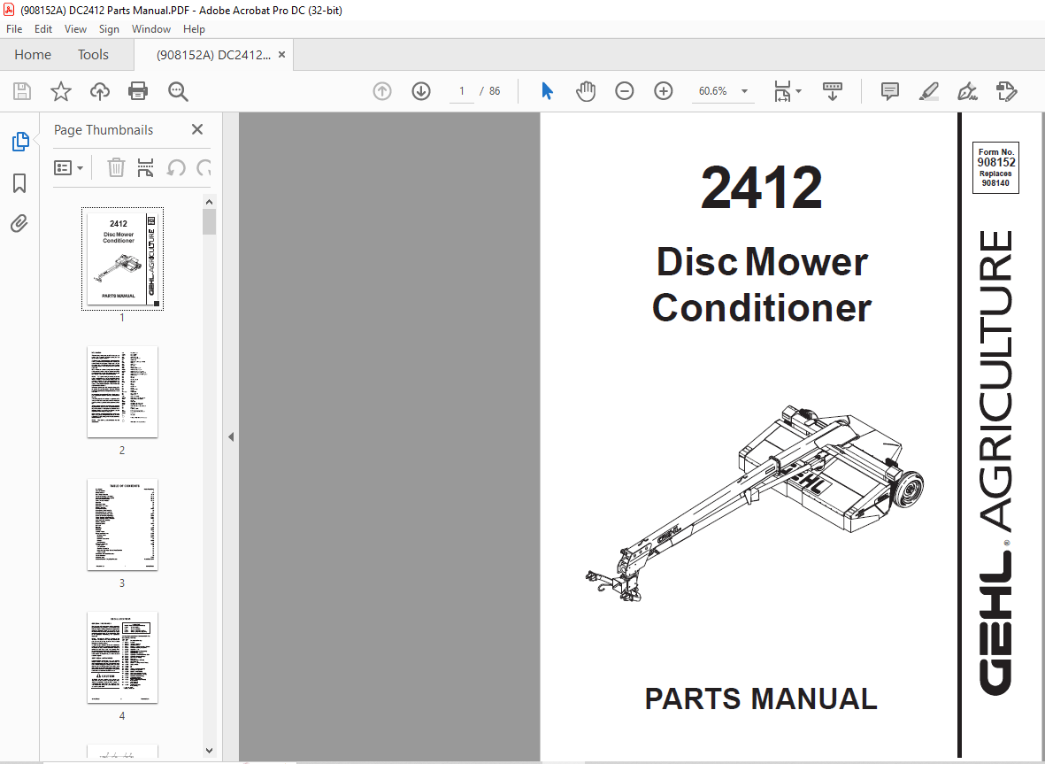
Gehl 2412 Disc Mower Conditioner Parts Manual 908152 – PDF DOWNLOAD
Gehl 2412 Disc Mower Conditioner Parts Manual 908152 – PDF DOWNLOAD
FILE DETAILS:
Gehl 2412 Disc Mower Conditioner Parts Manual 908152 – PDF DOWNLOAD
Language : English
Pages : 86
Downloadable : Yes
File Type : PDF
Size: 3.4 MB
TABLE OF CONTENTS:
Gehl 2412 Disc Mower Conditioner Parts Manual 908152 – PDF DOWNLOAD
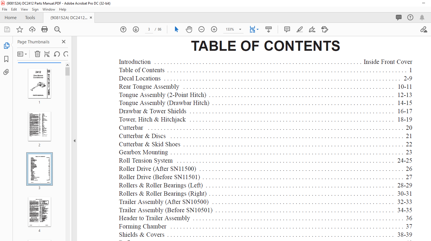
Introduction Inside Front Cover
Table of Contents 1
Decal Locations 2-9
Rear Tongue Assembly 10-11
Tongue Assembly (2-Point Hitch) 12-13
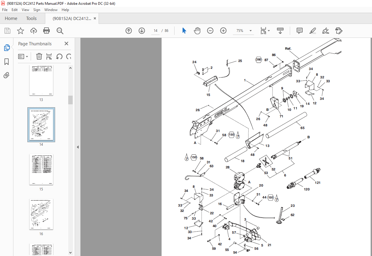
Tongue Assembly (Drawbar Hitch) 14-15
Drawbar & Tower Shields 16-17
Tower, Hitch & Hitchjack 18-19
Cutterbar 20
Cutterbar & Discs 21
Cutterbar & Skid Shoes 22
Gearbox Mounting 23
Roll Tension System 24-25
Roller Drive (After SN11500) 26
Roller Drive (Before SN11501) 27
Rollers & Roller Bearings (Left) 28-29
Rollers & Roller Bearings (Right) 30-31
Trailer Assembly (After SN10500) 32-33
Trailer Assembly (Before SN10501) 34-35
Header to Trailer Assembly 36
Forming Chamber 37
Shields & Covers 38-39
Deflector 40
Curtains 41
Hydraulics 42-47
Electrical 48-51
Axles & Wheels 52
Component Breakdowns 53-68
Universal Drives 53-61
Gearboxes 62-66
Hydraulic Components 67
Hitchjack 68-69
Hitch Extension 70
Options & Accessories 71-74
Safety Chain 71
Tall Skid Shoes 71
Wide Tire Bumper Kit 72
Crop Lifter Kit, V-Type Blades, Sway Chain Kit 73
Truck Hitch Kit 74
Service Kits – Electrical Connectors 75
Alphabetical Index 76
Numerical Index 77-82
Standard Hardware Torque Specifications Inside Back Cover
DESCRIPTION:
Gehl 2412 Disc Mower Conditioner Parts Manual 908152 – PDF DOWNLOAD
Introduction:
When ordering service parts, specify the correct part number, full description, quantity required, the unit model number and serial number. The Disc Mower Conditioner model and serial number is on a plate located on the left side of the Main Frame near the Drawbar anchor point.
- “Right” and “Left” are determined from a position standing behind the Disc Mower Conditioner. From this position the Drawbar is on the left. GEHL Company reserves the right to make changes or improvements in the design or construction of any part of the unit without incurring the obligation to install such changes on any previously delivered units.
- Refer to the abbreviations table located on this page for the various fastener descriptions. Standard attaching hardware torque values are also provided on the inside back cover. In the exploded view parts list, Reference Numbers may have additional information following the Reference Number.
- A Tear Drop symbol will indicate an application of a “wet” product such as oil, and the number inside the Tear Drop will correspond to the description in the Parts List. Also, a number inside a hexagon will be the torque value required, in foot pounds, on the associated Reference Number.
- Items shown in the parts list that do not have Reference Numbers are shown for reference purposes only and are NOT available for purchase. Unless otherwise specified, all Cap Screws or Bolts are Grade 5, zinc plated; Hexagon Nuts for Grade 5 Screws or Bolts are Grade B; Hexagon Nuts for other Screws or Bolts are Grade A.
IMAGES PREVIEW OF THE MANUAL:
More products