$29
Gehl 253, 303, 353, 373 Compact Excavator Service Manual 918148B – PDF DOWNLOAD
Gehl 253, 303, 353, 373 Compact Excavator Service Manual 918148B – PDF DOWNLOAD
FILE DETAILS:
Gehl 253, 303, 353, 373 Compact Excavator Service Manual 918148B – PDF DOWNLOAD
Language : English
Pages : 138
Downloadable : Yes
File Type : PDF
Size: 6.92 MB
IMAGES PREVIEW OF THE MANUAL:
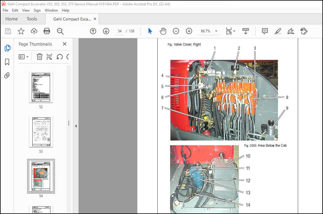
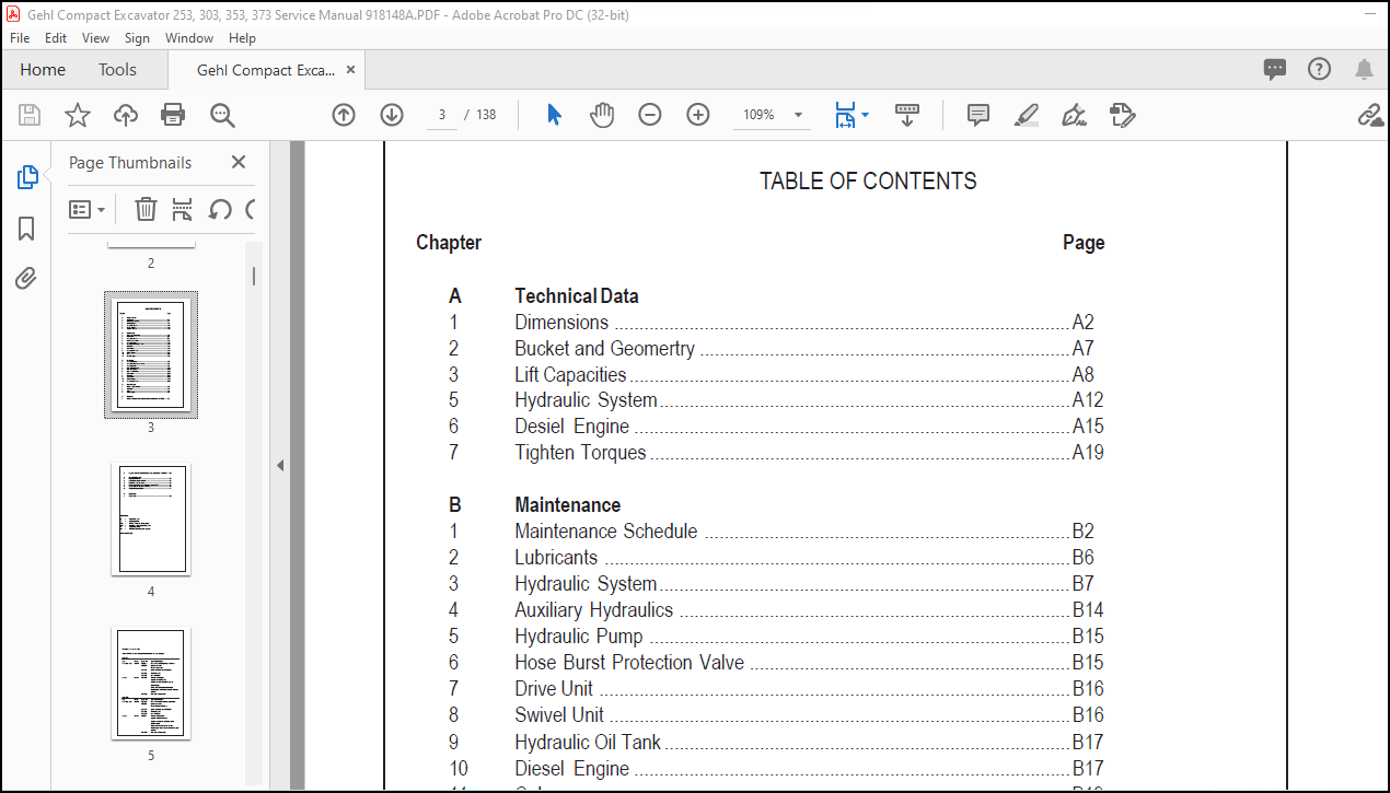
TABLE OF CONTENTS:
Gehl 253, 303, 353, 373 Compact Excavator Service Manual 918148B – PDF DOWNLOAD
A Technical Data
1 Dimensions ……………………………………………………………………………….A2
2 Bucket and Geomertry ………………………………………………………………..A7
3 Lift Capacities…………………………………………………………………………….A8
5 Hydraulic System……………………………………………………………………….A12
6 Desiel Engine ……………………………………………………………………………A15
7 Tighten Torques …………………………………………………………………………A19
B Maintenance
1 Maintenance Schedule ……………………………………………………………….B2
2 Lubricants …………………………………………………………………………………B6
3 Hydraulic System……………………………………………………………………….B7
4 Auxiliary Hydraulics ……………………………………………………………………B14
5 Hydraulic Pump …………………………………………………………………………B15
6 Hose Burst Protection Valve ……………………………………………………….B15
7 Drive Unit ………………………………………………………………………………….B16
8 Swivel Unit ………………………………………………………………………………..B16
9 Hydraulic Oil Tank ………………………………………………………………………B17
10 Diesel Engine ……………………………………………………………………………B17
11 Cab ………………………………………………………………………………………….B19
12 Undercarriage ……………………………………………………………………………B20
C Hydraulics
1 Hydraulic System ……………………………………………………………………….C2
2 Hydraulic Component Location …………………………………………………….C4
3 Hydraulic Pump ………………………………………………………………………….C6
4 Pilot Oil Supply Unit ……………………………………………………………………C11
5 Main Valve Block ……………………………………………………………………….C16
6 Pilot Control Valves …………………………………………………………………….C32
7 Swivel Unit ………………………………………………………………………………..C35
8 Drive Unit ………………………………………………………………………………….C42
9 Swivel Joint ……………………………………………………………………………….C52
10 Switch Valves …………………………………………………………………………….C55
13 Hydraulic Oil Tank ………………………………………………………………………C58
D Diesel Engine
1 Diesel Engine Overall ………………………………………………………………..D2
2 Alternator …………………………………………………………………………………..D4
3 Starter……………………………………………………………………………………….D4
4 Water Cooler ……………………………………………………………………………..D4
E Electrical
1 Diagram (Kabota Diesel Engine Starting at Serial No. AB00001) ……..E2
2 Diagram (Yanmar Diesel Engine Starting at Serial No. AD00001) …….E8
F Operation Elements
1 Major Components ……………………………………………………………………..F2
2 Cab Equipment and Controls ……………………………………………………….F3
3 Instrument Panel Functions …………………………………………………………F4
4 Hydraulic Connections for Additional Attachments………………………….F6
5 Brakes and Swivel Lock Mechanism ……………………………………………F6
6 Tilting the Superstrucure ……………………………………………………………..F7
G Attachment
1 Bucket List ………………………………………………………………………………..G2
More products