$33
Gehl 280 Wheel Loader Parts Manual 918113 – PDF DOWNLOAD
Gehl 280 Wheel Loader Parts Manual 918113 – PDF DOWNLOAD
FILE DETAILS:
Gehl 280 Wheel Loader Parts Manual 918113 – PDF DOWNLOAD
Language : English
Pages : 182
Downloadable : Yes
File Type : PDF
Size: 17.8 MB
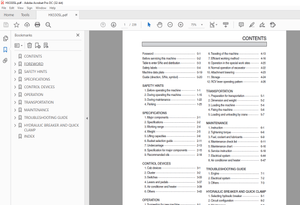
TABLE OF CONTENTS:
Gehl 280 Wheel Loader Parts Manual 918113 – PDF DOWNLOAD
INTRODUCTION 1
DECALS
DECALS – GENERAL INFORMATION 2
DECALS 3
ENGINE MOUNTING 1000178993 – (SN 341020591 AND UP) 5
ENGINE MOUNTING 1000130438 – (SN 341020017-341020590) 7
ENGINE BLOCK 1000178995 – (SN 341020591 AND UP) 9
ENGINE BLOCK 1000130439 – (SN 341020017-341020590) 11
CYLINDER HEAD 1000178998 – (SN 341020591 AND UP) 13
CYLINDER HEAD 1000130440 – (SN 341020017-341020590) 15
LUBRICATION 1000179031 – (SN 341020591 AND UP) 17
LUBRICATION 1000130370 – (SN 341020017-341020590) 19
INJECTION SYSTEM 1000179034 – (SN 341020591 AND UP) 21
INJECTION SYSTEM 1000130480 – (SN 341020017-341020590) 23
WATER PUMP, FAN & STARTER 1000130595 25
FUEL TANK 1000130599 27
AIR FILTER 1000128926 29
EXHAUST COMPONENTS 1000130517 31
THROTTLE PEDAL 1000128958 33
RADIATOR 1000130518 35
VARIABLE DISPLACEMENT PUMP 1000128963 38
VARIABLE DISPLACEMENT PUMP (CONT.) 1000128966 41
PRESSURE LIMIT RELIEF VALVE HYDRAULICS 1000162823 43
HYDRAULIC MOTOR 1000128969 45
INCHING DEVICE 1000128980 47
HYDRAULIC CIRCUIT 1000128992 49
AXLES 1000129726 52
FRONT AXLE 1000177203 54
STEERING (FRONT AND REAR AXLE) 1000177204 56
WHEEL HUB (FRONT AND REAR AXLE) 1000129019 58
LOCKING DIFFERENTIAL (FRONT AXLE) 1000129069 60
REAR AXLE 1000129070 62
LOCKING DIFFERENTIAL (REAR AXLE) 1000129072 64
GEAR BOX 1000129083 66
PARKING BRAKE 1000129739 68
HYDRAULIC INSTALLATION – STEERING 1000129743 71
OIL TANK 1000129981 74
HYDRAULIC INSTALLATION – PILOT VALVE 1000129093 77
3RD HYDRAULIC CIRCUIT 1000129905 79
LIFT ARM CIRCUIT 1000129906 81
LIFT CYLINDER 1000130393 83
CONTROL VALVE 1000129192 85
PILOT VALVE – FLOAT POSITION 1000130372 87
AUXILIARY CONTROL CIRCUIT 1000179222 – (SN 341020682 AND UP) 89
AUXILIARY CONTROL CIRCUIT 1000168435 – (SN 341020314 – 341020681) 93
AUXILIARY CONTROL CIRCUIT 1000130036 – (SN 341020313 AND BEFORE) 96
AUXILIARY HIGH FLOW CIRCUIT (FRONT) 1000179168 – (SN 341020682 AND UP) 99
AUXILIARY HIGH FLOW CIRCUIT (FRONT) 1000166562 – (SN 341020314 – 341020681) 102
AUXILIARY HIGH FLOW CIRCUIT (FRONT)1000130061 – (SN 341020313 AND BEFORE) 105
LIFT CYLINDER/TILT CYLINDER 1000130124 108
CAB – ELECTRICAL 1000129885 110
MOUNT SET – ELECTRICAL 1000163879 113
WORK LIGHTS 1000129340 115
WORK LIGHTS – FRONT (OPTION) 809273 118
ROTATING BEACON (OPTION) 809309 120
RADIO (OPTION) 809263 122
BATTERY 1000129352 124
MAIN HARNESS 1000178197 – (SN 341020591 AND UP) 126
MAIN HARNESS 1000129813 – (SN 341020017-341020590) 128
WIRE HARNESS – CAB 1000129808 130
WIRE HARNESS – ROOF 1000127843 132
BRAKE LIGHT 1000127846 134
TIRES 1000129372 136
FRAME/COUNTERWEIGHTS 1000129752 138
LIFT ARM 1000129744 140
CAB FLOOR 1000128028 143
TRIM 1000129394 145
TRIM 1000129395 147
CAB 1000127964 149
CAB DOOR 1000127984 152
CAB TRIM 1000128023 155
CAB TRIM (CONT.) 1000129936 157
OPERATOR’S SEAT (FOR ROPS MACHINES) 1000128029 159
OPERATOR’S SEAT (FOR CAB MACHINES) 1000112484 161
ROPS PROTECTION BARS 1000147468 163
HEATER 1000129900 165
TOOLS 1000129534 167
BUCKETS 1000130142 169
PALLET FORKS (48″) 1000129550 171
SKID-A-TACH PLATE 809262 173
TORQUE SPECIFICATIONS 175
DESCRIPTION:
Gehl 280 Wheel Loader Parts Manual 918113 – PDF DOWNLOAD
INTRODUCTION:
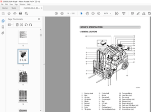
When ordering service parts, specify the correct part number, full description, quantity required, the unit model number and serial number. For your safety and continued proper operation, use only genuine GEHL service parts. The model and serial number for this unit are on a tag located on a panel on the front of the cab.
- ”Right” and ”left” are determined from a position sitting on the seat and facing forward. MANITOU AMERICAS, INC. reserves the right to make changes or improvements in the design or construction of any part of the unit without incurring the obligation to install such changes on any previously delivered units.
- Refer to the abbreviations table located on this page for the various fastener descriptions. Standard attaching hardware torque values are also provided on the inside back cover. Metric torque values shown in the illustrations are in Newtonmeters and can be converted to foot-pounds by multiplying by 0.738.
- Specific Reference Numbers, indicating a complete assembly, are circled in some illustrations. A small bag, pictured in some illustrations, indicates a seal kit (seals, o-rings, etc.). In the exploded view parts list, additional information may follow the Reference Number.
Serial number breaks are indicated as follows:
• (SN 999 and before) – indicates serial numbers
up to and including 999.
• (SN 1000 – 2000) – indicates serial numbers
between 1000 and 2000.
• (SN 999 and up) – indicates serial numbers
including 999 and after.
Serial number exceptions and inclusion are
indicated as follows:
• (SN 999 and before except 997) – indicates
serial numbers up to and including 999,
EXCEPT 997.
• (SN 1000 – 2000 except 1996 including 997) –
indicates serial numbers between 1000 and
2000, INCLUDING 997 EXCEPT 1996.
• (SN 2001 and up including 1996) – indicates
serial numbers including 2001 and after,
INCLUDING 1996.
IMAGES PREVIEW OF THE MANUAL:


More products