$33
Gehl 383Z Compact Excavator Service Manual 918197A – PDF DOWNLOAD
Gehl 383Z Compact Excavator Service Manual 918197A – PDF DOWNLOAD
FILE DETAILS:
Gehl 383Z Compact Excavator Service Manual 918197A – PDF DOWNLOAD
Language : English
Pages : 174
Downloadable : Yes
File Type : PDF
Size: 9.5 MB
IMAGES PREVIEW OF THE MANUAL:
DESCRIPTION:
Gehl 383Z Compact Excavator Service Manual 918197A – PDF DOWNLOAD
Operation:
1.1 General Information:
- Your decision to purchase the Gehl compact excavator was a good one. We are sure that
your decision was carefully considered and that you are looking forward to many years of
reliable performance from the machine. - Gehl Company has invested much time and effort in developing its lines of equipment. The
machine you have purchased is built with a great deal of pride, and designed to provide
long life, efficient operation, durability and dependability. - Modern machinery has become more sophisticated and, with that in mind, Gehl Company
asks that you read and COMPLETELY understand the contents of this manual and
become familiar with the new machine, BEFORE attempting to service it. - This manual was developed specifically for the machine you have purchased. The information
within is for your assistance in preparing, adjusting, maintaining and servicing the
machine. More importantly, this manual provides a service plan for safe and proper servicing
of the machine. Refer to the Table of Contents for an outline (by chapters) of this manual. - Use the Index, located at the back of this manual, for specific chapter and topic/page
number references. - If the machine was purchased “used,” or if the owner’s address has changed, please provide
your Gehl dealer or Gehl Company with the owner’s name and current address, along
with the machine model and serial number. This will allow the registered owner information
to be updated, so that the owner can be notified directly in case of an important product
issue, such as a safety update program. - “Right” and “left” are determined from the position of sitting in the operator’s seat, facing
forward. - Gehl Company reserves the right to make changes or improvements in the design or construction
of any part without incurring the obligation to install such changes on any unit
previously delivered. - Throughout this manual information is provided that is introduced by the word NOTE or
TABLE OF CONTENTS:
Gehl 383Z Compact Excavator Service Manual 918197A – PDF DOWNLOAD
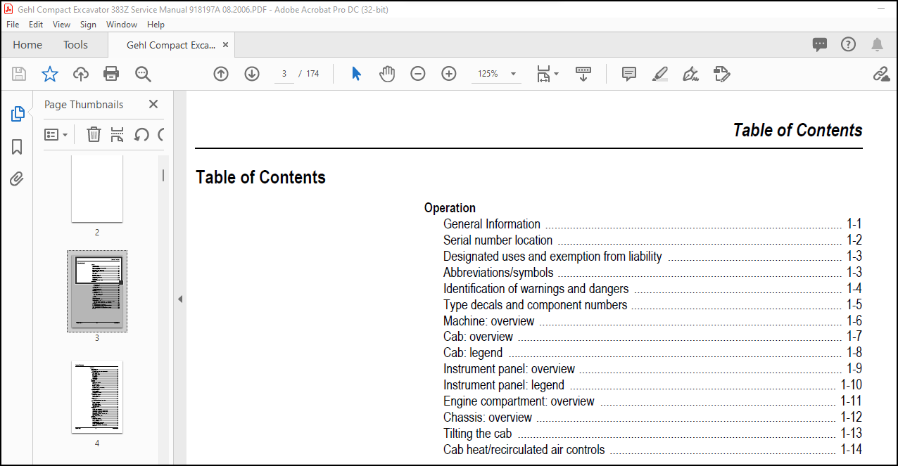
Operation
General Information ……………………………………………………………………………………. 1-1
Serial number location ………………………………………………………………………………… 1-2
Designated uses and exemption from liability ………………………………………………… 1-3
Abbreviations/symbols ………………………………………………………………………………… 1-3
Identification of warnings and dangers ………………………………………………………….. 1-4
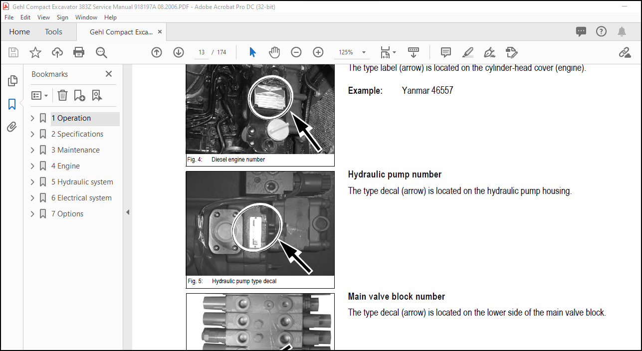
Type decals and component numbers …………………………………………………………… 1-5
Machine: overview ……………………………………………………………………………………… 1-6
Cab: overview ……………………………………………………………………………………………. 1-7
Cab: legend ………………………………………………………………………………………………. 1-8
Instrument panel: overview ………………………………………………………………………….. 1-9
Instrument panel: legend …………………………………………………………………………… 1-10
Engine compartment: overview ………………………………………………………………….. 1-11
Chassis: overview …………………………………………………………………………………….. 1-12
Tilting the cab ………………………………………………………………………………………….. 1-13
Cab heat/recirculated air controls ……………………………………………………………….. 1-14
Specifications
Chassis …………………………………………………………………………………………………….. 2-1
Engine ………………………………………………………………………………………………………. 2-1
Fuel injection pump ………………………………………………………………………………. 2-2
Engine capacities …………………………………………………………………………………. 2-2
Engine tightening torques ………………………………………………………………………. 2-2
Hydraulic system ……………………………………………………………………………………….. 2-3
Auxiliary hydraulics oil flow …………………………………………………………………….. 2-3
Undercarriage and swivel unit ……………………………………………………………………… 2-4
Dozer blade ………………………………………………………………………………………………. 2-4
Screwable hose burst valve ……………………………………………………………………. 2-4
Electrical system ………………………………………………………………………………………… 2-5
Fuse box in instrument panel …………………………………………………………………. 2-5
Main fuse box with relays ………………………………………………………………………. 2-5
Relays …………………………………………………………………………………………………. 2-6
Noise levels ………………………………………………………………………………………………. 2-6
Coolant compound table ……………………………………………………………………………… 2-6
Model-specific tightening torques …………………………………………………………………. 2-7
General tightening torques ………………………………………………………………………….. 2-7
Tightening torques for hydraulic screw connections (dry assembly) …………….. 2-7
Tightening torques for high-resistance screw connections ………………………….. 2-9
Dimensions ……………………………………………………………………………………………… 2-10
Standard Long Dipper Arm Load Diagram …………………………………………………… 2-11
Standard Long Dipper Arm with Counterweight Load Diagram ……………………….. 2-12
Optional Short Dipper Arm Load Diagram ……………………………………………………. 2-13
Optional Short Dipper Arm with Counterweight Load Diagram ……………………….. 2-14
Kinematics ………………………………………………………………………………………………. 2-15
918197/AP0806 i-2 Printed in U.S.A
Table of Contents
Maintenance
Fluids and lubricants ………………………………………………………………………………….. 3-1
Maintenance label ………………………………………………………………………………………. 3-3
Explanation of symbols on the maintenance label ……………………………………… 3-3
Maintenance schedule ………………………………………………………………………………… 3-5
Check, clean or inspect …………………………………………………………………………. 3-5
Fluid and filter changes ………………………………………………………………………….. 3-6
Air conditioning …………………………………………………………………………………….. 3-6
Functional check …………………………………………………………………………………… 3-6
Leakage check ……………………………………………………………………………………… 3-7
Daily lubrication ……………………………………………………………………………………. 3-7
Service packages ……………………………………………………………………………………… 3-10
Introduction ……………………………………………………………………………………………… 3-10
Fuel system ……………………………………………………………………………………………… 3-11
Specific safety instructions …………………………………………………………………… 3-11
Refueling ……………………………………………………………………………………………. 3-11
Stationary fuel pumps ………………………………………………………………………….. 3-12
Bleeding the fuel system ………………………………………………………………………. 3-12
Emptying the fuel tank …………………………………………………………………………. 3-13
Fuel shut-off valve and water separator …………………………………………………. 3-13
Replacing the fuel filter ………………………………………………………………………… 3-14
Engine lubrication system ………………………………………………………………………….. 3-15
Checking the oil level …………………………………………………………………………… 3-15
Adding engine oil ………………………………………………………………………………… 3-16
Changing engine oil and filter ……………………………………………………………….. 3-17
Cooling system ………………………………………………………………………………………… 3-18
Specific safety instructions …………………………………………………………………… 3-18
Checking/adding coolant ……………………………………………………………………… 3-19
Draining coolant ………………………………………………………………………………….. 3-20
Air filter ……………………………………………………………………………………………………. 3-21
Replacing the filter ………………………………………………………………………………. 3-22
Weekly functional check of the dust valve ………………………………………………. 3-23
V-belt ………………………………………………………………………………………………………. 3-24
Checking V-belt tension ……………………………………………………………………….. 3-24
Tightening the V-belt ……………………………………………………………………………. 3-25
Air conditioning V-belt check ………………………………………………………………… 3-26
Tightening the V-belt of the
air conditioning system ………………………………………………………………………… 3-26
Pressure check ………………………………………………………………………………………… 3-27
General ……………………………………………………………………………………………… 3-27
Checking pilot control pressure …………………………………………………………….. 3-27
Variable displacement pump P1 pressure check ……………………………………… 3-28
Variable displacement pump P2 pressure check ……………………………………… 3-29
Pressure check of gear pump P3 ………………………………………………………….. 3-30
Secondary pressure limiting valve of the gear motor ………………………………… 3-31
Measuring ports: overview ……………………………………………………………………. 3-32
Primary pressure limiting valves ……………………………………………………………. 3-32
Test report ……………………………………………………………………………………………….. 3-33
Hydraulic system ………………………………………………………………………………………. 3-37
Specific safety instructions …………………………………………………………………… 3-37
Checking the hydraulic oil level …………………………………………………………….. 3-38
Adding hydraulic oil ……………………………………………………………………………… 3-39
Changing hydraulic oil …………………………………………………………………………. 3-39
Monitoring the hydraulic oil return filter …………………………………………………… 3-40
Checking hydraulic pressure lines …………………………………………………………. 3-41
Checking the final drive oil level and adding oil ……………………………………….. 3-42
Draining oil …………………………………………………………………………………………. 3-42
Printed in U.S.A. i-3 918197/AP0806
Table of Contents
Tracks …………………………………………………………………………………………………….. 3-43
Checking track tension ………………………………………………………………………… 3-43
Track Tension …………………………………………………………………………………….. 3-44
Lubrication strip ……………………………………………………………………………………….. 3-45
Lubrication strip ………………………………………………………………………………….. 3-45
Attachment maintenance ……………………………………………………………………… 3-45
Electrical system ………………………………………………………………………………………. 3-46
Safety instructions ………………………………………………………………………………. 3-46
Regular service/maintenance ……………………………………………………………….. 3-47
Specific component instructions ……………………………………………………………. 3-47
Alternator …………………………………………………………………………………………… 3-47
Battery ………………………………………………………………………………………………. 3-48
Jump-starting the engine ……………………………………………………………………… 3-49
Cab ………………………………………………………………………………………………………… 3-50
Replacing the inside heater filter …………………………………………………………… 3-50
General maintenance ……………………………………………………………………………….. 3-51
Cleaning ……………………………………………………………………………………………. 3-51
General instructions for all areas …………………………………………………………… 3-51
Inside the cab …………………………………………………………………………………….. 3-52
Seat belt ……………………………………………………………………………………………. 3-52
Exterior of the machine ………………………………………………………………………… 3-52
Engine compartment …………………………………………………………………………… 3-52
Screw connections and attachments ……………………………………………………… 3-52
Pivots and hinges ……………………………………………………………………………….. 3-52
Engine
3TNV88-PNS engine: overview ……………………………………………………………………. 4-1
Fuel system ………………………………………………………………………………………………. 4-3
Checking and adjusting valve tip clearance ……………………………………………………. 4-4
Order for loosening/tightening cylinder head bolts ………………………………………….. 4-5
Checking the injection nozzles …………………………………………………………………….. 4-6
Pressure check …………………………………………………………………………………….. 4-6
Checking the nozzle jet ……………………………………………………………………………….. 4-6
Injection time ……………………………………………………………………………………………… 4-7
Checking injection time ………………………………………………………………………….. 4-7
Setting injection time …………………………………………………………………………….. 4-8
Fuel injection pump replacement …………………………………………………………….. 4-8
Adjusting engine RPM ………………………………………………………………………………. 4-10
Compression ……………………………………………………………………………………………. 4-10
Checking the coolant thermostat ………………………………………………………………… 4-10
Checking the thermal switch ………………………………………………………………………. 4-11
Oil pressure switch …………………………………………………………………………………… 4-11
Checking the coolant circuit ……………………………………………………………………….. 4-12
Engine troubleshooting …………………………………………………………………………….. 4-13
Hydraulic system
Hydraulic pump PVD-2B44BP-16G5-4713F …………………………………………………… 5-1
Pump unit: exploded view ………………………………………………………………………. 5-3
Pilot oil supply unit ………………………………………………………………………………… 5-4
Main valve block ………………………………………………………………………………………… 5-5
Ports …………………………………………………………………………………………………… 5-5
Legend ………………………………………………………………………………………………… 5-6
Main valve block diagram ………………………………………………………………………. 5-7
Pressure limiting valves …………………………………………………………………………. 5-8
Pump assignment …………………………………………………………………………………. 5-9
Drive counterbalancing system …………………………………………………………………… 5-10
Pump assignment for drive counterbalancing …………………………………………. 5-10
918197/AP0806 i-4 Printed in U.S.A
Table of Contents
Regeneration – dipper arm section ……………………………………………………………… 5-11
Bucket pre-tension ……………………………………………………………………………………. 5-11
Flow rate adjustment of auxiliary hydraulics …………………………………………………. 5-12
Pilot valves ………………………………………………………………………………………………. 5-13
Joystick ……………………………………………………………………………………………… 5-13
Pilot valve (driving) ……………………………………………………………………………… 5-14
Pilot valve for auxiliary hydraulics ………………………………………………………….. 5-16
Valves …………………………………………………………………………………………………….. 5-17
7/2 directional valve (changeover valve) ………………………………………………… 5-17
Changeover valve for SAE/ISO controls …………………………………………………. 5-18
Travel drive – SN AB00855 and after (see page 5-22 for SN up to AB00854) …… 5-19
Function …………………………………………………………………………………………….. 5-20
Travel drive – SN up to AB00854 (see page 5-19 for SN AB00854 and after) …… 5-22
Function …………………………………………………………………………………………….. 5-23
Swivel motor ……………………………………………………………………………………………. 5-25
Parking brake/multidisc brake function …………………………………………………… 5-26
Swivel joint ………………………………………………………………………………………………. 5-29
Sealing ………………………………………………………………………………………………. 5-29
Breather filter …………………………………………………………………………………………… 5-30
Troubleshooting in the hydraulic system ………………………………………………………. 5-31
Hydraulics diagram …………………………………………………………………………………… 5-32
Hydraulics diagram (legend) ………………………………………………………………………. 5-33
Hydraulics diagram …………………………………………………………………………………… 5-35
Main valve block diagram ………………………………………………………………………….. 5-36
Electrical system
Ohm’s Law (current, voltage, resistance); power …………………………………………….. 6-1
Measuring equipment and methods ………………………………………………………………. 6-1
Cable color coding ……………………………………………………………………………………… 6-3
Relays ………………………………………………………………………………………………………. 6-3
Use, mode of function ……………………………………………………………………………. 6-3
Electrical units ……………………………………………………………………………………………. 6-4
Fuse box in instrument panel ……………………………………………………………………….. 6-4
Main fuse box/relays …………………………………………………………………………………… 6-4
Relays ………………………………………………………………………………………………………. 6-4
Socket ………………………………………………………………………………………………………. 6-4
Tip switches on joystick ………………………………………………………………………………. 6-5
Left-hand side joystick …………………………………………………………………………… 6-5
Right-hand side joystick …………………………………………………………………………. 6-5
Alternator ………………………………………………………………………………………………….. 6-6
Starter ………………………………………………………………………………………………………. 6-6
Wiring diagram: legend ……………………………………………………………………………….. 6-8
Wiring diagram …………………………………………………………………………………………… 6-9
Engine wiring harness: legend ……………………………………………………………………. 6-10
Engine wiring harness ……………………………………………………………………………….. 6-11
Cab wiring harness: legend ……………………………………………………………………….. 6-12
Cab wiring harness …………………………………………………………………………………… 6-13
Roof wiring harness ………………………………………………………………………………….. 6-14
Printed in U.S.A. i-5 918197/AP0806
Table of Contents
Options
Air conditioning ………………………………………………………………………………………….. 7-1
Specific safety instructions …………………………………………………………………….. 7-1
Specifications ………………………………………………………………………………………. 7-1
Components ………………………………………………………………………………………… 7-2
Filling the air conditioning system ……………………………………………………………. 7-4
Maintenance ………………………………………………………………………………………… 7-6
Troubleshooting ……………………………………………………………………………………. 7-8
Counterweight ……………………………………………………………………………………………. 7-9
Specifications ………………………………………………………………………………………. 7-9
Short dipper arm ………………………………………………………………………………………… 7-9
Specifications ………………………………………………………………………………………. 7-9
Auxiliary hydraulics connections …………………………………………………………………. 7-10
Proportional controls …………………………………………………………………………………. 7-11
Function …………………………………………………………………………………………….. 7-11
Ports …………………………………………………………………………………………………. 7-11
Overview ……………………………………………………………………………………………. 7-12
Wiring harness ……………………………………………………………………………………. 7-13
Control unit plug assignment ………………………………………………………………… 7-14
Safety features …………………………………………………………………………………… 7-14
Procedure in case of malfunction ………………………………………………………….. 7-15
Diagnosis display ………………………………………………………………………………… 7-15
More products