$30
Gehl 4010 Series SL4510 Gasoline SL4610 Skid Loader Shop Manual 903931 – PDF DOWNLOAD
Gehl 4010 Series SL4510 Gasoline SL4610 Skid Loader Shop Manual 903931 – PDF DOWNLOAD
FILE DETAILS:
Gehl 4010 Series SL4510 Gasoline SL4610 Skid Loader Shop Manual 903931 – PDF DOWNLOAD
Language : English
Pages : 104
Downloadable : Yes
File Type : PDF
Size: 3.3 MB
IMAGES PREVIEW OF THE MANUAL:
DESCRIPTION:
Gehl 4010 Series SL4510 Gasoline SL4610 Skid Loader Shop Manual 903931 – PDF DOWNLOAD
INTRODUCTION:
This manual has been written and illustrated to help you, the serviceman, in troubleshooting and servicing the SL4010 Series (SL4510, SL4610, SL4515* & SL4615*) Skid Loaders. The material in this manual is the latest in factory service information. It has been compiled by our factory Service Department and Engineering personnel to give you the best service information available. Follow all procedures carefully, to avoid unnecessary delays and/ or damage to the equipment.
- Where procedures are given in a step-by-step manner, follow them in the order given. Although we have outlined assembly and disassembly procedures for you to follow, there are probably alternate methods that could also work. The Hydraulic System and the Engine are the two most important parts of an SL4010 Series Skid Loader.
- When any service is performed on the Hydraulics System, always clean the hydraulic component and fittings, before disconnecting any hydraulic lines. Contamination is the greatest cause of failure in Hydraulics Systems. For any Engine repairs, consult your Ford or Perkins Engine Service Manual.
- The SL45 l O or SL45 l 5* model Loader uses the Ford 98 CID Gasoline Engine. The SL4610 or SL4615* model Loader uses the Perkins 4.108 Diesel Engine. The Model and Serial Numbers Plate, for the SL4010 Series Skid Loaders, is located inside the Right Chassis Riser, between the Lift Arm and Lift Cylinder Pivots.
- “Right” and “Left” are determined from a position sitting on the Seat and facing forward. From this position, the Traction (Propulsion) Control T-Bar is on the “left” and the Lift/Tilt Control T-Bar is on the “right”. The Ford 98 CID Engine has an identification decal affixed to the right side of the rocker cover.
- The decal contains the engine serial number, which differentiates that engine from any other. · Besides the serial number, there is the displacement (that determines the engine specifications), the model number and, the SO (Special Options) number (which determines the parts or components required on this unit). When requesting information or ordering replacement parts for this engine, BE SURE to provide all the numbers.
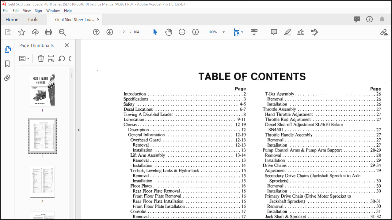
TABLE OF CONTENTS:
Gehl 4010 Series SL4510 Gasoline SL4610 Skid Loader Shop Manual 903931 – PDF DOWNLOAD
Introduction 2
Specifications 3
Safety 4-5
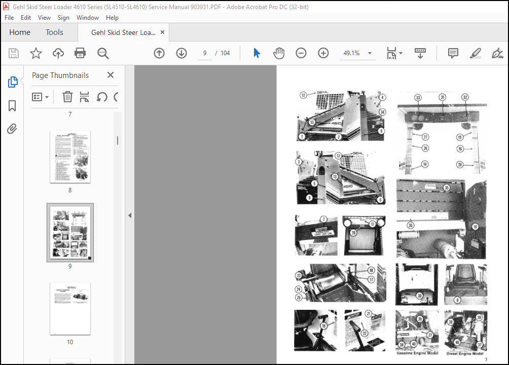
Decal Locations 6-7
Towing A Disabled Loader 8
Lubrication 9-11
Chassis 12-19
Description 12
General Information 12-19
Overhead Guard 12-13
Removal 12-13
Installation 13
Lift Arm Assembly 13-14
Removal 13
Installation 14
Tri-link, Leveling Links & Hydro-lock 15
Removal • 15
Installation I 5
Floor Plates 16
Rear Floor Plate Removal 16
Front Floor Plate Removal 16
Rear Floor Plate Installation 16
Front Floor Plate Installation 16
Consoles 17
Removal 17
Installation 17
Chain Case & Access Covers 18
Removal 18
Installation 18
Fuel Tank 19
Removal 19
Installation 19
Drive 20-34
Brakes 20-23
Disc Brakes Adjustment-Before SN3251-SL4510 &
SN3601-SL4610 20
Brake Pad Replacement-Before SN3251-SL4510 &
SN360I-SL4610 20
Disc Brake Adjustment-After SN3250-SL45!0 &
SN3600-SL4610 20
Brake Pad Replacement-After SN3250-SL4510 &
SN3600-SL46!0 21
Removal 21
Installation 21
Brake Cables-Before SN3251-SL45!0 &
SN3601-SL4610 22
Removal 22
Installation 22
Brake Cables-After SN3250-SL45!0 &
SN3600-SL4610 23
Removal 23
Installation 23
Traction Drive T-Bar 24-25
Detent Adjustment 24
Drive Linkage Neutral Adjustment 24
Stop Cam Adjustment 24
T-Bar Assembly 25
Removal 25
Installation 25
Lift/Tilt T-Bar 26
Control Linkage Adjustment 26
Page
T-Bar Assembly 26
Removal 26
Installation 26
Throttle Assembly 27
Hand Throttle Adjustment 27
Throttle Rod Adjustment 27
Diesel Shut-off Adjustment-SL46 I O Before
SN4501 27
Throttle Handle Assembly 27
Removal 27
Installation 27
Pump Control Arms & Pump Arm Support 28-29
Removal 28
Installation 29
Drive Chains 29-34
Adjustment 29
Secondary Drive Chains (Jackshaft Sprocket to Axle
Sprockets) 30
Removal 30
Installation 30
Primary Drive Chain (Drive Motor Sprocket to
Jackshaft Sprocket) 30-31
Removal 30
Installation 31
Jack Shaft & Sprocket 31-32
Removal 31
Installation 31-32
Axle & Sprocket 32-33
Removal 32
Installation 32-33
Wheel Bearings 33-34
Removal 33-34
Installation 34
Hydrostatic System 35-56
Introduction 35-38
Neutral 36
Forward 37
Reverse 38
Turns 38
Troubleshooting 39-42
Hydrostatic Testing 43-44
Propulsion Pump and Drive Motor 43
Charge Pressure 43
Charge Inlet Pressure • 43-44
General Information 44-56
Tandem Pump 44-45
Removal 44-45
Installation 45
Tandem Pump Breakdown 45-50
Disassembly 45-48
Parts Wear Inspection 49
Reassembly 49-50
Pump Drive Coupling 50-52
Removal 50-51
Installation 51-52
Hydrostatic Drive Motor 52-53
Removal 52
Installation 52-53
Drive Motors Breakdown 53-54
Disassembly 53-54
Inspection 54
Page
Reassembly 54
Hydrostatic Drive Motor Mounting Plate & Drive
Sprocket-Before SN3251-SL4510 &
SN3601-SL4610 54-55
Removal 54-55
Installation 55
Hydrostatic Drive Motor Mounting Plate & Drive
Sprocket-After SN3250-SL4510 &
SN3600-SL4610 55-56
Removal 55-56
Installation 56
Hydraulics System 57-75
Introduction 57
Toubleshooting 58-59
Hydraulic Component Testing 60-61
Control Valve Relief Pressure 60
Lift & Tilt System Pump 60
Tilt Cylinder 60
Lift Cylinder 60-61
General Information 61-75
Tilt Cylinders 61
Removal 61
Installation 6 I
Lift Cylinders 61-62
Removal 61
Installation 61-62
Lift & Tilt Cylinders Breakdown 63
Disassembly 63
Reassembly 63
Lift & Tilt System Gear Pump 64
Disassembly 64
Reassembly 64
Lift & Tilt System Pump Breakdown 65
Disassembly 65-66
Pump Parts Inspection 66
General 66
Gear Assembly 66
Body 66
Cover 66
Reassembly 66
Hydraulic Oil Filter 66-67
Removal 66-67
Installation 67
Hydraulic Oil Strainer 67
Removal 67
Installation 67
Cleaning Hydraulic Oil Strainer 67
Self-Leveling Relief Valve (1200 PSI) 67-68
Removal 67
Service 68
Installation 68
Self-Leveling By-Pass Relief Valve (1000 PSI) 70
Removal 70
Service 70
Installation 70
Control Valve 71
Removal :· 71
Installation 71
Control Valve Breakdown 73-74
Disassembly 73
Reassembly 73-74
Page
Auxiliary Valve 74
Back Pressure Poppet (Super Charge Valve) 75
Removal 75
Installation 7 5
Electrical System 76-79
Troubleshooting 76
SL4610 Electrical System Diagram 77
SL45 l O Electrical System Diagram 78
Light Mounting Kit 79
Engines 80-98
Introduction 80-81
SL4510 Gasoline-powered Engine 80
SL46 l O Diesel-powered Engine 80-81
Ordering Engine Parts 8 I
Troubleshooting 81-82
International Symbols Explanation 83
General Information 84-98
SL4610 Engine Oil Filter 84
Removal 84
Installation 84
SL45 l O Engine Oil Filter 84
Removal 84
Installation 84
Air Cleaner 84-85
Removal 84
Installation 84-85
Air Cleaner Element 85
Removal 85
Cleaning 85
SL4610 Starter 85
Removal 85
Installation 85
SL45 l O Starter 86
Removal 86
Installation 86
SL45 l O & SL46 l O Engine Exhaust Assemblies 87
Removal 87
Installation 87
SL4610 Radiator & Oil Cooler 87-89
Removal 87-88
Installation 88-89
SL4510 Radiator & Oil Cooler 89-91
Removal 89
Installation 89-91
SL4610 Alternator Belt Adjustment 91
SL45 l O Alternator Belt Adjustment 91
SL4510 (Only) Governor Belt Adjustment 91
SL4510 (Only) Governor & Carburetor Adjustment 92
SL4510 (Only) Carburetor 92-94
Removal 92
Installation 93
Dwell Angle Check 93
Dynamic Dwell Angle Adjustment 93
Ignition Timing 93-94
SL46 I O Engine 95-96
Removal 95
Installation 95-96
SL4510 Engine 96-98
Removal 96-98
Installation 98/
More products