$32
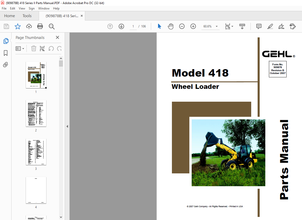
Gehl 418 Wheel Loader Parts Manual 909878 – PDF DOWNLOAD
Gehl 418 Wheel Loader Parts Manual 909878 – PDF DOWNLOAD
FILE DETAILS:
Gehl 418 Wheel Loader Parts Manual 909878 – PDF DOWNLOAD
Language : English
Pages : 106
Downloadable : Yes
File Type : PDF
Size: 3.93 MB
TABLE OF CONTENTS:
Gehl 418 Wheel Loader Parts Manual 909878 – PDF DOWNLOAD
Introduction……………………………………………i
Table of Contents…………………………………..1
Decals ………………………………………………….3
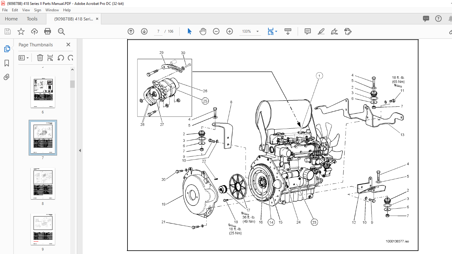
Engine Mounts………………………………………5
Engine Block ………………………………………..6
Cylinder Head……………………………………….7
Fuel Injection ………………………………………..8
Water Pump ………………………………………….9
Fuel Filter……………………………………………10
Fuel Line…………………………………………….11
Fuel Tank ……………………………………………12
Air Cleaner………………………………………….13
Engine Cooling System ………………………..14
Engine Cooling Bulkhead……………………..15
Throttle ………………………………………………16
Frame …………………………………………………17
Variable Displacement Pump Installation .18
Variable Displacement Pump ………………..19
Hydraulic Drive Motor Installation ………..20
Hydraulic Drive Motor …………………………21
Front Axle Attachment …………………………22
Front Axle…………………………………………..23
Front Axle Drive………………………………….24
Differential………………………………………….25
Front Axle Planetary Drive……………………26
Service Brake………………………………………27
Brake Caliper ………………………………………28
Parking Brake ……………………………………..29
Rear Axle Attachment 1 ……………………….30
Rear Axle Attachment 2 ……………………….31
Rear Axle Drive…………………………………..32
Planetary …………………………………………….33
Transfer Case ………………………………………34
Tires …………………………………………………..35
Steering Unit 1…………………………………….36
Steering Unit 2…………………………………….37
Screw Joint………………………………………….37
Screw …………………………………………………37
Steering Cylinder …………………………………38
Operator’s Seat ……………………………………39
Operator’s Seat Base…………………………….40
Fenders……………………………………………….41
Engine Cover ………………………………………42
Engine Exhaust ……………………………………43
Instrument Panel Installation …………………44
Battery………………………………………………..45
Lighting………………………………………………46
Optional Lighting…………………………………47
Engine Wiring Harness…………………………48
Main Wiring Harness……………………………49
Front Wiring Harness …………………………..50
Burst Valve Wiring Harness………………….51
Glow System……………………………………….52
Cab…………………………………………………….53
Windows…………………………………………….54
Cab Door…………………………………………….55
Cab Trim…………………………………………….56
Windshield Washer System…………………..57
Front Window Guard……………………………58
Hydraulic Oil Tank………………………………59
Hydraulic Oil Tank Attachment …………….60
Return Line Control Valve ……………………61
Control Valve Installation……………………..62
Control Valve with 3rd Control Circuit…..63
Control Lever………………………………………64
Control Valve………………………………………65
Input/Output Element …………………………..66
Valve Block Cylinder …………………………..67
3rd Control Circuit Valve Block…………….68
Cross Union ………………………………………..69
Joystick ………………………………………………70
Hydraulic Control Valve Installation 1……71
Hydraulic Control Valve Installation 2……72
Load Stabilizer…………………………………….73
Pressure Line Solenoid Valve………………..74
Lift Arm ……………………………………………..75
Hose Routing ………………………………………76
Quick Hitch…………………………………………77
Lift and Tilt Cylinders ………………………….78
Lift and Tilt Cylinders ………………………….79
Lift Cylinder Hose Burst Valve……………..80
Tilt Cylinder Hose Burst Valve ……………..81
Tilt Cylinder Restrictor…………………………82
Heater…………………………………………………83
Bucket ………………………………………………..84
Numerical Index ………………………………….87
DESCRIPTION:
Gehl 418 Wheel Loader Parts Manual 909878 – PDF DOWNLOAD
INTRODUCTION:
When ordering service parts, specify the correct part number, full description, quantity required, the unit model number and serial number. For your safety and continued proper operation, use only genuine GEHL service parts. The model and serial number for this unit are on a tag located on a panel on the front of the cab.
- ”Right” and ”left” are determined from a position sitting on the seat and facing forward. MANITOU AMERICAS, INC. reserves the right to make changes or improvements in the design or construction of any part of the unit without incurring the obligation to install such changes on any previously delivered units.
- Refer to the abbreviations table located on this page for the various fastener descriptions. Standard attaching hardware torque values are also provided on the inside back cover. Metric torque values shown in the illustrations are in Newtonmeters and can be converted to foot-pounds by multiplying by 0.738.
- Specific Reference Numbers, indicating a complete assembly, are circled in some illustrations. A small bag, pictured in some illustrations, indicates a seal kit (seals, o-rings, etc.). In the exploded view parts list, additional information may follow the Reference Number.
Serial number breaks are indicated as follows:
• (SN 999 and before) – indicates serial numbers
up to and including 999.
• (SN 1000 – 2000) – indicates serial numbers
between 1000 and 2000.
• (SN 999 and up) – indicates serial numbers
including 999 and after.
Serial number exceptions and inclusion are
indicated as follows:
• (SN 999 and before except 997) – indicates
serial numbers up to and including 999,
EXCEPT 997.
• (SN 1000 – 2000 except 1996 including 997) –
indicates serial numbers between 1000 and
2000, INCLUDING 997 EXCEPT 1996.
• (SN 2001 and up including 1996) – indicates
serial numbers including 2001 and after,
INCLUDING 1996.
IMAGES PREVIEW OF THE MANUAL:

More products