$33
Gehl 480T All-Wheel-Steer Loader Parts Manual 918119 – PDF DOWNLOAD
Gehl 480T All-Wheel-Steer Loader Parts Manual 918119 – PDF DOWNLOAD
FILE DETAILS:
Gehl 480T All-Wheel-Steer Loader Parts Manual 918119 – PDF DOWNLOAD
Language : English
Pages : 108
Downloadable : Yes
File Type : PDF
Size: 5.6 MB
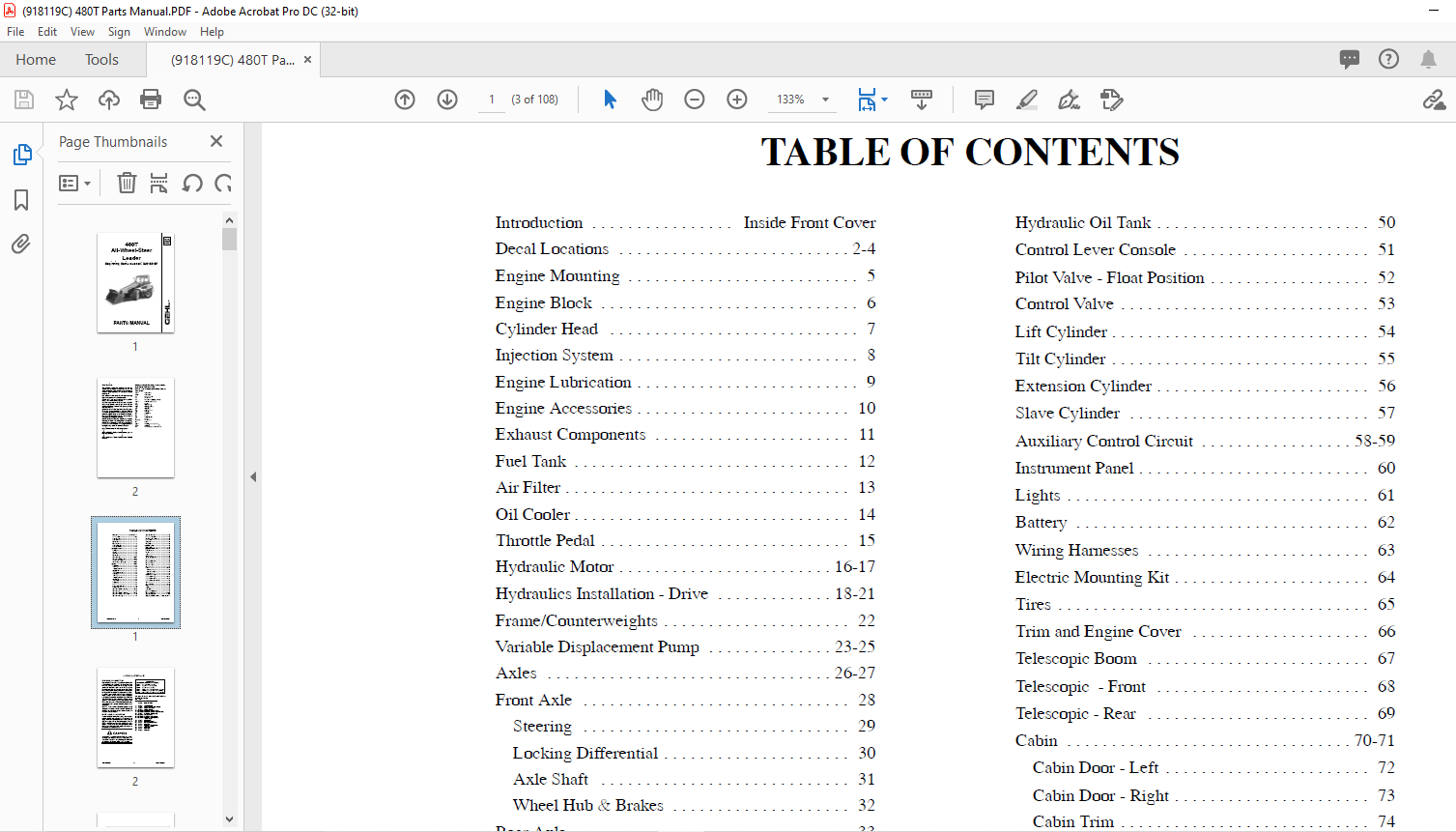
TABLE OF CONTENTS:
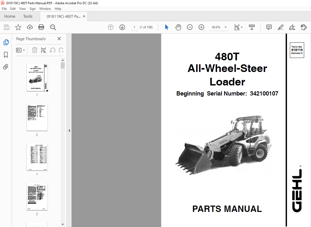
Gehl 480T All-Wheel-Steer Loader Parts Manual 918119 – PDF DOWNLOAD
Beginning Serial Number: 342100107
Introduction . . . . . . . . . . . . . . . . Inside Front Cover
Decal Locations . . . . . . . . . . . . . . . . . . . . . . . . . . 2-4
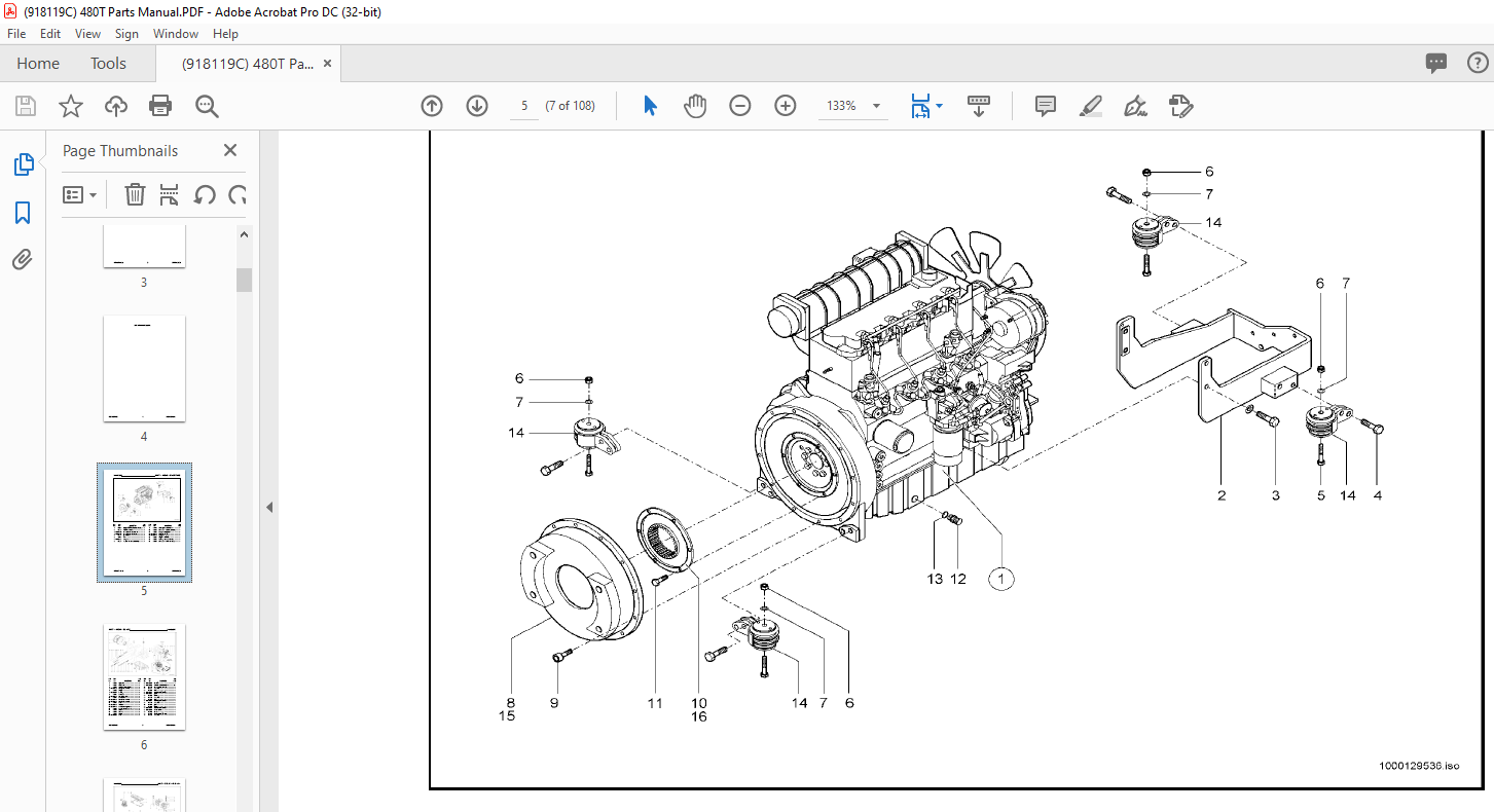
Engine Mounting . . . . . . . . . . . . . . . . . . . . . . . . . . 5
Engine Block . . . . . . . . . . . . . . . . . . . . . . . . . . . . . 6
Cylinder Head . . . . . . . . . . . . . . . . . . . . . . . . . . . . 7
Injection System . . . . . . . . . . . . . . . . . . . . . . . . . . . 8
Engine Lubrication . . . . . . . . . . . . . . . . . . . . . . . . . 9
Engine Accessories . . . . . . . . . . . . . . . . . . . . . . . . 10
Exhaust Components . . . . . . . . . . . . . . . . . . . . . . 11
Fuel Tank . . . . . . . . . . . . . . . . . . . . . . . . . . . . . . . 12
Air Filter . . . . . . . . . . . . . . . . . . . . . . . . . . . . . . . . 13
Oil Cooler . . . . . . . . . . . . . . . . . . . . . . . . . . . . . . . 14
Throttle Pedal . . . . . . . . . . . . . . . . . . . . . . . . . . . . 15
Hydraulic Motor . . . . . . . . . . . . . . . . . . . . . . . . 16-17
Hydraulics Installation – Drive . . . . . . . . . . . . . 18-21
Frame/Counterweights . . . . . . . . . . . . . . . . . . . . . 22
Variable Displacement Pump . . . . . . . . . . . . . . 23-25
Axles . . . . . . . . . . . . . . . . . . . . . . . . . . . . . . . . 26-27
Front Axle . . . . . . . . . . . . . . . . . . . . . . . . . . . . . . 28
Steering . . . . . . . . . . . . . . . . . . . . . . . . . . . . . . 29
Locking Differential . . . . . . . . . . . . . . . . . . . . . 30
Axle Shaft . . . . . . . . . . . . . . . . . . . . . . . . . . . . 31
Wheel Hub & Brakes . . . . . . . . . . . . . . . . . . . . 32
Rear Axle . . . . . . . . . . . . . . . . . . . . . . . . . . . . . . . 33
Steering . . . . . . . . . . . . . . . . . . . . . . . . . . . . . . 34
Locking Differential . . . . . . . . . . . . . . . . . . . . . 35
Axle Shaft . . . . . . . . . . . . . . . . . . . . . . . . . . . . 36
Wheel Hub . . . . . . . . . . . . . . . . . . . . . . . . . . . . 37
Gearbox . . . . . . . . . . . . . . . . . . . . . . . . . . . . . . . . 38
Gears . . . . . . . . . . . . . . . . . . . . . . . . . . . . . . . . . . 39
Service Brake – Hydraulics . . . . . . . . . . . . . . . . . . 40
Parking Brake . . . . . . . . . . . . . . . . . . . . . . . . . . . . 41
Hydraulics Installation – Steering . . . . . . . . . . . 42-43
Hydraulic Pump . . . . . . . . . . . . . . . . . . . . . . . . 44-45
Hydraulics Installation – Pilot Valve . . . . . . . . . 46-47
Hydraulics Installation – Control Valve . . . . . . . . . 48
Hydraulics – Telescopic . . . . . . . . . . . . . . . . . . . . 49
Hydraulic Oil Tank . . . . . . . . . . . . . . . . . . . . . . . . 50
Control Lever Console . . . . . . . . . . . . . . . . . . . . . 51
Pilot Valve – Float Position . . . . . . . . . . . . . . . . . . 52
Control Valve . . . . . . . . . . . . . . . . . . . . . . . . . . . . 53
Lift Cylinder . . . . . . . . . . . . . . . . . . . . . . . . . . . . . 54
Tilt Cylinder . . . . . . . . . . . . . . . . . . . . . . . . . . . . . 55
Extension Cylinder . . . . . . . . . . . . . . . . . . . . . . . . 56
Slave Cylinder . . . . . . . . . . . . . . . . . . . . . . . . . . . 57
Auxiliary Control Circuit . . . . . . . . . . . . . . . . . 58-59
Instrument Panel . . . . . . . . . . . . . . . . . . . . . . . . . . 60
Lights . . . . . . . . . . . . . . . . . . . . . . . . . . . . . . . . . . 61
Battery . . . . . . . . . . . . . . . . . . . . . . . . . . . . . . . . . 62
Wiring Harnesses . . . . . . . . . . . . . . . . . . . . . . . . . 63
Electric Mounting Kit . . . . . . . . . . . . . . . . . . . . . . 64
Tires . . . . . . . . . . . . . . . . . . . . . . . . . . . . . . . . . . . 65
Trim and Engine Cover . . . . . . . . . . . . . . . . . . . . 66
Telescopic Boom . . . . . . . . . . . . . . . . . . . . . . . . . 67
Telescopic – Front . . . . . . . . . . . . . . . . . . . . . . . . 68
Telescopic – Rear . . . . . . . . . . . . . . . . . . . . . . . . . 69
Cabin . . . . . . . . . . . . . . . . . . . . . . . . . . . . . . . . 70-71
Cabin Door – Left . . . . . . . . . . . . . . . . . . . . . . . 72
Cabin Door – Right . . . . . . . . . . . . . . . . . . . . . . 73
Cabin Trim . . . . . . . . . . . . . . . . . . . . . . . . . . . . 74
Quickhitch Assembly . . . . . . . . . . . . . . . . . . . . . . 75
Operator’s Seat – Upper . . . . . . . . . . . . . . . . . . 76-77
Operator’s Seat – Lower . . . . . . . . . . . . . . . . . . 78-79
Operator’s Seat – Attachments . . . . . . . . . . . . . . . 80
Heater . . . . . . . . . . . . . . . . . . . . . . . . . . . . . . . . . . 81
Air Conditioning . . . . . . . . . . . . . . . . . . . . . . . 82-83
Tools . . . . . . . . . . . . . . . . . . . . . . . . . . . . . . . . . . 84
Buckets . . . . . . . . . . . . . . . . . . . . . . . . . . . . . . . . . 85
Pallet Forks . . . . . . . . . . . . . . . . . . . . . . . . . . . . . 86
Alphabetical Index . . . . . . . . . . . . . . . . . . . . . . . . 87
Numerical Index . . . . . . . . . . . . . . . . . . . . . . . 88-102
Hydraulic Fitting Data . . . . . . . . . . . . . . . . . . . . 103
Torque Specifications Chart . . . . . Inside Rear Cover
DESCRIPTION:
Gehl 480T All-Wheel-Steer Loader Parts Manual 918119 – PDF DOWNLOAD
INTRODUCTION:
When ordering service parts, specify the correct part number, full description, quantity required, the unit model number and serial number. For your safety and continued proper operation, use only genuine GEHL service parts. The model and serial number for this unit are on a tag located on a panel on the front of the cabin.
- ”Right” and ”left” are determined from a position sitting on the seat and facing forward. MANITOU AMERICAS, INC. reserves the right to make changes or improvements in the design or construction of any part of the unit without incurring the obligation to install such changes on any previously delivered units.
- Refer to the abbreviations table located on this page for the various fastener descriptions. Standard attaching hardware torque values are also provided on the inside back cover. Metric torque values shown in the illustrations are in Newtonmeters and can be converted to foot-pounds by multiplying by 0.738.
- Specific Reference Numbers, indicating a complete assembly, are circled in some illustrations. A small bag, pictured in some illustrations, indicates a seal kit (seals, o-rings, etc.). In the exploded view parts list, additional information may follow the Reference Number.
IMAGES PREVIEW OF THE MANUAL:
More products