$33
Gehl 503Z Compact Excavator Service Manual 918159 – PDF DOWNLOAD
Gehl 503Z Compact Excavator Service Manual 918159 – PDF DOWNLOAD
FILE DETAILS:
Gehl 503Z Compact Excavator Service Manual 918159 – PDF DOWNLOAD
Language : English
Pages : 206
Downloadable : Yes
File Type : PDF
Size: 23.6 MB
IMAGES PREVIEW OF THE MANUAL:
DESCRIPTION:
Gehl 503Z Compact Excavator Service Manual 918159 – PDF DOWNLOAD
Serial Number AC02471 and up
Operation
General information
Your decision to purchase the Gehl compact excavator was a good one. We are sure that
your decision was carefully considered and that you are looking forward to many years of
reliable performance from the machine.
Gehl Company has invested much time and effort in developing its lines of equipment. The
equipment you have purchased is built with a great deal of pride, and designed to provide
long life, efficient operation, durability and dependability.
Modern machinery has become more sophisticated and, with that in mind, Gehl Company
asks that you read and COMPLETELY understand the contents of this manual and
become familiar with the new machine, BEFORE attempting to service it.
This manual was developed specifically for the machine you have purchased. The information
within is for your assistance in preparing, adjusting, maintaining and servicing the
machine. More important, this manual provides a service plan for safe and proper servicing
of the machine. Refer to the Table of Contents for an outline (by chapters) of this manual.
Use the Index, located at the back of this manual, for specific chapter and topic/page
number references.
If the machine is resold, Gehl Company recommends that this manual be given to the new
owner.
If the machine was purchased “used,” or if the owner’s address has changed, please provide
your Gehl dealer or Gehl Company with the owner’s name and current address, along
with the machine model and serial number. This will allow the registered owner information
to be updated, so that the owner can be notified directly in case of an important product
issue, such as a safety update program.
“Right” and “left” are determined from the position of sitting in the operator’s seat, facing
forward.
Gehl Company reserves the right to make changes or improvements in the design or construction
of any part without incurring the obligation to install such changes on any unit
previously delivered.
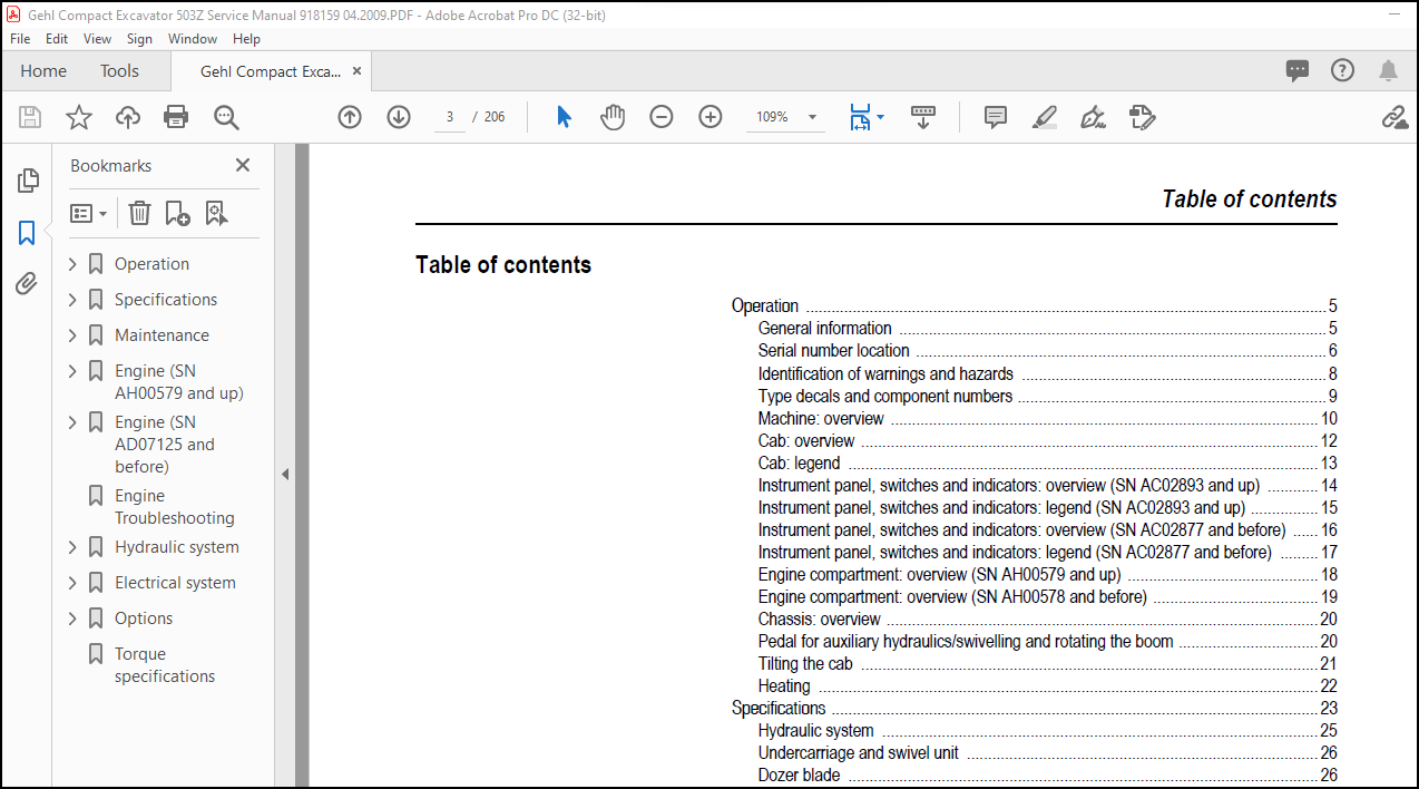
TABLE OF CONTENTS:
Gehl 503Z Compact Excavator Service Manual 918159 – PDF DOWNLOAD
Operation……………………………………………………………………………………….. 7
General information…………………………………………………………………………… 7
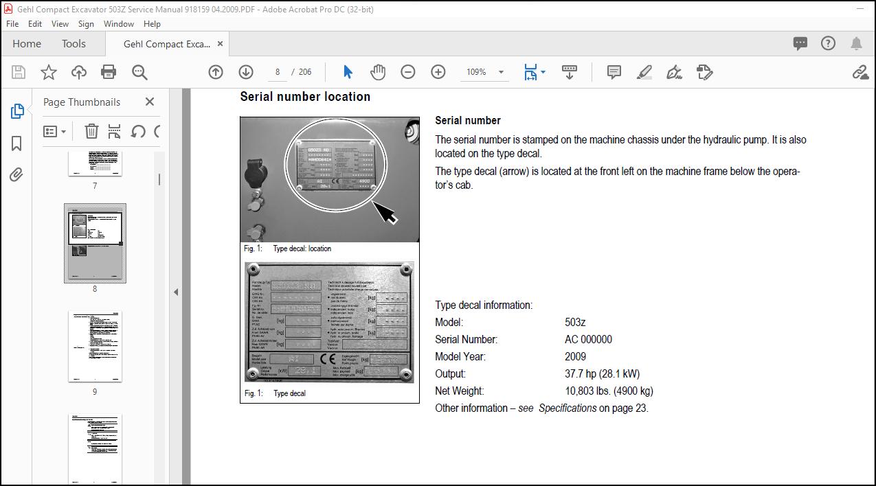
Serial number location………………………………………………………………………… 8
Identification of warnings and hazards………………………………………………………….. 10
Type decals and component numbers………………………………………………………………. 11
Machine: overview…………………………………………………………………………….. 12
Cab: overview………………………………………………………………………………… 14
Cab: legend………………………………………………………………………………….. 15
Instrument panel, switches and indicators: overview (SN AC02893 and up)…………………………….. 16
Instrument panel, switches and indicators: legend (SN AC02893 and up)………………………………. 17
Instrument panel, switches and indicators: overview (SN AC02877 and before)…………………………. 18
Instrument panel, switches and indicators: legend (SN AC02877 and before)…………………………… 19
Engine compartment: overview (SN AH00579 and up)…………………………………………………. 20
Engine compartment: overview (SN AH00578 and before)……………………………………………… 21
Chassis: overview…………………………………………………………………………….. 22
Pedal for auxiliary hydraulics/swivelling and rotating the boom……………………………………. 22
Tilting the cab………………………………………………………………………………. 23
Heating……………………………………………………………………………………… 24
Preheated fresh air……………………………………………………………………….. 24
Specifications…………………………………………………………………………………… 25
Frame……………………………………………………………………………………….. 25
Engine………………………………………………………………………………………. 25
Fuel injection pump…………………………………………………………………………… 26
Engine capacities…………………………………………………………………………….. 26
Engine tightening torques……………………………………………………………………… 26
Hydraulic system……………………………………………………………………………… 27
Auxiliary hydraulics oil flow………………………………………………………………. 28
Undercarriage and swivel unit………………………………………………………………….. 28
Dozer blade………………………………………………………………………………….. 28
Electrical system…………………………………………………………………………….. 29
Fuse box in instrument panel……………………………………………………………….. 29
Main fuse box with relays under the cab……………………………………………………… 29
Relays…………………………………………………………………………………… 30
Sound levels…………………………………………………………………………………. 30
Coolant compound table………………………………………………………………………… 30
Model-specific tightening torques………………………………………………………………. 31
General tightening torques…………………………………………………………………….. 31
Tightening torques for hydraulic screw connections (dry assembly)………………………………. 31
Tightening torques for high- resistance screw connections……………………………………… 33
503Z dimensions………………………………………………………………………………. 34
Lift capacity table with short dipper arm……………………………………………………….. 35
Lift capacity table with long dipper arm………………………………………………………… 36
Lift capacity table with short dipper arm and counterweight……………………………………….. 37
Lift capacity table with long dipper arm and counterweight………………………………………… 38
Bucket geometry………………………………………………………………………………. 39
Maintenance……………………………………………………………………………………… 41
Fluids and lubricants…………………………………………………………………………. 41
Additional oil change and filter replacement (hydraulics)……………………………………… 42
Maintenance decal…………………………………………………………………………….. 43
Explanation of symbols on the maintenance decal………………………………………………. 43
Maintenance schedule (overview)………………………………………………………………… 45
Introduction…………………………………………………………………………………. 49
Fuel system………………………………………………………………………………….. 50
Specific safety instructions……………………………………………………………….. 50
Refuelling……………………………………………………………………………….. 50
Stationary fuel pumps……………………………………………………………………… 51
Diesel fuel specification………………………………………………………………….. 51
Bleeding the fuel system…………………………………………………………………… 51
Emptying the fuel tank…………………………………………………………………….. 52
Fuel pre-filter with water separator………………………………………………………… 52
Replacing the fuel filter………………………………………………………………….. 53
Engine lubrication system……………………………………………………………………… 54
Checking the oil level…………………………………………………………………….. 54
Adding engine oil…………………………………………………………………………. 55
Changing engine oil……………………………………………………………………….. 55
Replacing the engine oil filter cartridge……………………………………………………. 56
Cooling system……………………………………………………………………………….. 57
Specific safety instructions……………………………………………………………….. 57
Checking/adding coolant……………………………………………………………………. 58
Draining coolant………………………………………………………………………….. 59
Air filter…………………………………………………………………………………… 60
Replacing the filter………………………………………………………………………. 61
Weekly functional check of the dust valve……………………………………………………. 62
V-belt………………………………………………………………………………………. 62
Checking V-belt tension……………………………………………………………………. 63
Tightening the V-belt……………………………………………………………………… 63
Checking the air conditioning V-belt………………………………………………………… 64
Tightening the air conditioning V-belt………………………………………………………. 65
Pressure check……………………………………………………………………………….. 66
General………………………………………………………………………………….. 66
Checking pilot control pressure…………………………………………………………….. 66
Pressure check of variable displacement pump P1………………………………………………. 67
Pressure check of variable displacement pump P2………………………………………………. 68
Pressure check of gear pump P3……………………………………………………………… 69
Secondary pressure limiting valve of the gear motor…………………………………………… 70
Measuring ports: overview………………………………………………………………….. 70
Primary pressure limiting valves……………………………………………………………. 71
Test report………………………………………………………………………………….. 73
Hydraulic system……………………………………………………………………………… 77
Specific safety instructions……………………………………………………………….. 77
Checking the hydraulic oil level……………………………………………………………. 78
Adding hydraulic oil………………………………………………………………………. 79
Changing hydraulic oil…………………………………………………………………….. 79
Monitoring the hydraulic oil return filter…………………………………………………… 80
Checking hydraulic pressure lines…………………………………………………………… 81
Travel drive…………………………………………………………………………………. 82
Checking the oil level and adding oil……………………………………………………….. 82
Draining oil……………………………………………………………………………… 82
Tracks………………………………………………………………………………………. 83
Checking track tension…………………………………………………………………….. 83
Setting the tracks………………………………………………………………………… 84
Lubrication work……………………………………………………………………………… 85
Dozer blade lubrication points……………………………………………………………… 85
Swivel console lubrication points…………………………………………………………… 86
Boom lubrication points……………………………………………………………………. 86
Dipper arm lubrication points………………………………………………………………. 87
Lubrication strip…………………………………………………………………………. 87
Maintenance of attachments…………………………………………………………………. 87
Electrical system…………………………………………………………………………….. 88
Safety instructions……………………………………………………………………….. 88
Service and maintenance work at regular intervals…………………………………………….. 89
Instructions concerning specific components………………………………………………….. 89
Alternator……………………………………………………………………………….. 89
Battery………………………………………………………………………………….. 90
Using a Booster Battery (Jump-Starting)……………………………………………………… 91
Cab…………………………………………………………………………………………. 92
Replacing the cab filter…………………………………………………………………… 92
General maintenance work………………………………………………………………………. 93
General instructions for all areas of the machine…………………………………………….. 93
Inside the cab……………………………………………………………………………. 93
The seat belt…………………………………………………………………………….. 94
Exterior of the machine……………………………………………………………………. 94
Engine compartment………………………………………………………………………… 94
Screw connections and attachments…………………………………………………………… 94
Pivots and hinges…………………………………………………………………………. 94
Long-term storage…………………………………………………………………………….. 95
Before storage……………………………………………………………………………. 95
During storage……………………………………………………………………………. 95
After storage…………………………………………………………………………….. 95
Engine (SN AH00579 and up)………………………………………………………………………… 97
Engine marked 4TNV88-BPNS (SN AH00579 and up): overview…………………………………………… 97
Fuel system………………………………………………………………………………….. 99
Preparing for cylinder head removal……………………………………………………………..100
Checking and adjusting valve tip clearance……………………………………………………….100
Removing/Tightening order for cylinder head bolts…………………………………………………101
Checking the injection nozzles………………………………………………………………….102
Pressure check…………………………………………………………………………….102
Checking the nozzle jet………………………………………………………………………..102
Injection timing………………………………………………………………………………103
Checking injection timing…………………………………………………………………..103
Adjusting injection timing………………………………………………………………….103
Replacement of fuel injection pump…………………………………………………………..104
Adjusting engine speeds………………………………………………………………………..106
Compression…………………………………………………………………………………..107
Checking the coolant thermostat…………………………………………………………………107
Checking the thermal switch…………………………………………………………………….108
Oil pressure switch……………………………………………………………………………108
Checking the coolant circuit……………………………………………………………………108
Engine (SN AD07125 and before)……………………………………………………………………..109
Engine marked 4TNV88-PNS (SN AD07125 and before): overview…………………………………………109
Fuel system…………………………………………………………………………………..111
Checking and adjusting valve tip clearance……………………………………………………….112
Removing/Tightening order for cylinder head bolts…………………………………………………112
Checking the injection nozzles………………………………………………………………….113
Pressure check…………………………………………………………………………….113
Checking the nozzle jet………………………………………………………………………..114
Injection timing………………………………………………………………………………114
Checking injection timing…………………………………………………………………..114
Adjusting injection timing………………………………………………………………….115
Replacement of fuel injection pump…………………………………………………………..115
Adjusting engine speeds………………………………………………………………………..118
Compression…………………………………………………………………………………..118
Checking the coolant thermostat…………………………………………………………………118
Checking the thermal switch…………………………………………………………………….119
Oil pressure switch……………………………………………………………………………119
Checking the coolant circuit……………………………………………………………………120
Engine Troubleshooting…………………………………………………………………………….121
Hydraulic system………………………………………………………………………………….123
Hydraulic pump: PVD-2B-41BP-16G5-4713F (SN AH00579 and up) PVD-2B-44BP-16G5-4713F (AD07125 and before)….123
Pump unit: exploded view……………………………………………………………………125
Pilot oil supply unit………………………………………………………………………126
Main valve block………………………………………………………………………………127
Ports…………………………………………………………………………………….127
Legend……………………………………………………………………………………127
Main valve block diagram……………………………………………………………………128
Pressure limiting valves……………………………………………………………………129
Auxiliary hydraulics pressure limiting valves…………………………………………………130
Pump assignment……………………………………………………………………………131
Drive counterbalancing system…………………………………………………………………..132
Pump assignment for drive counterbalancing……………………………………………………132
Drive counterbalancing system diagram………………………………………………………..133
Regeneration – dipper arm section……………………………………………………………….134
Bucket pre-tension…………………………………………………………………………….134
Flow rate adjustment for auxiliary hydraulics…………………………………………………….135
Pilot valves………………………………………………………………………………….136
Joystick………………………………………………………………………………….136
Pilot valve for auxiliary hydraulics…………………………………………………………140
Pilot valve for dozer blade…………………………………………………………………141
Valves……………………………………………………………………………………….142
7/2 directional valve (changeover valve)……………………………………………………..142
Shuttle valve block………………………………………………………………………..143
Changeover valve for SAE/ISO controls (option)………………………………………………..144
Travel drive………………………………………………………………………………….145
Function………………………………………………………………………………….146
2nd speed range function……………………………………………………………………146
Swivel unit…………………………………………………………………………………..148
Parking brake/multi-disc brake function………………………………………………………149
Swivel joint………………………………………………………………………………….152
Swivel joint servicing:…………………………………………………………………….153
Breather filter……………………………………………………………………………….153
Troubleshooting the hydraulic system…………………………………………………………….154
Hydraulics diagram (legend)…………………………………………………………………….155
Options diagram………………………………………………………………………………. 0
Main valve block diagram 503Z………………………………………………………………….. 0
Hydraulics diagram 503Z……………………………………………………………………….. 0
Electrical system…………………………………………………………………………………161
Ohm’s Law (defines current, voltage and resistance relationship)……………………………………161
Measuring equipment and methods…………………………………………………………………161
Cable color coding…………………………………………………………………………….162
Relays……………………………………………………………………………………….163
Use, mode of function………………………………………………………………………163
Electrical units………………………………………………………………………………163
Fuse box in instrument panel……………………………………………………………………163
Main fuse box with relays………………………………………………………………………164
Relays……………………………………………………………………………………….164
Socket……………………………………………………………………………………….165
Joystick switch buttons………………………………………………………………………..165
Joystick (left)……………………………………………………………………………165
Joystick (right)…………………………………………………………………………..165
Instrument panel: overview……………………………………………………………………..166
Switches overview (SN AC02893 and up)……………………………………………………………167
Switches overview (SN AC02877 and below)…………………………………………………………167
Alternator……………………………………………………………………………………168
Starter………………………………………………………………………………………168
Wiring harness overview………………………………………………………………………..168
Wiring diagram (SN AC02890 and up)……………………………………………………………… 0
Wiring diagram legend (SN AC02889 and before)……………………………………………………. 0
Wiring diagram (SN AC02889 and before)………………………………………………………….. 0
Engine – chassis wiring harness legend………………………………………………………….. 0
Engine – chassis wiring harness………………………………………………………………… 0
Wiring harness switches (SN AC02890 and up)……………………………………………………… 0
Wiring diagram legend (SN AC02890 and up)……………………………………………………….. 0
Wiring harness switches legend (SN AC02889 and before)……………………………………………. 0
Wiring harness switches (SN AC02889 and before)………………………………………………….. 0
Cab roof wiring harness……………………………………………………………………….. 0
Armrest wiring harness………………………………………………………………………… 0
Boom working light wiring harness………………………………………………………………. 0
Options………………………………………………………………………………………….183
Air conditioning………………………………………………………………………………183
Specific safety instructions………………………………………………………………..183
Specifications…………………………………………………………………………….183
Installation: overview……………………………………………………………………..184
Components………………………………………………………………………………..185
Adding refrigerating agent to the air conditioning system………………………………………187
Maintenance……………………………………………………………………………….188
Troubleshooting……………………………………………………………………………189
Air-suspension seat……………………………………………………………………………190
Connections……………………………………………………………………………….190
Counterweight…………………………………………………………………………………190
Specifications…………………………………………………………………………….190
Long dipper arm……………………………………………………………………………….191
Specifications…………………………………………………………………………….191
Auxiliary hydraulics connections………………………………………………………………..191
Quick-couplers…………………………………………………………………………….192
Attachments……………………………………………………………………………….192
Proportional controls………………………………………………………………………….193
Function………………………………………………………………………………….193
Two-speed variable auxiliary hydraulic mode selection………………………………………….193
Auxiliary hydraulics proportional joystick control…………………………………………….194
Auxiliary hydraulic hammer operation…………………………………………………………194
Ports…………………………………………………………………………………….195
Wiring harness…………………………………………………………………………….195
Control unit………………………………………………………………………………195
Control valve plug assignment……………………………………………………………….196
Safety features……………………………………………………………………………197
Measures to be taken in case of malfunctions………………………………………………….197
Diagnostic display…………………………………………………………………………198
Auto-idle feature (SN AH00579 and up)……………………………………………………………199
Function………………………………………………………………………………….199
Installation overview………………………………………………………………………200
Torque specifications……………………………………………………………………………..203
More products