$20
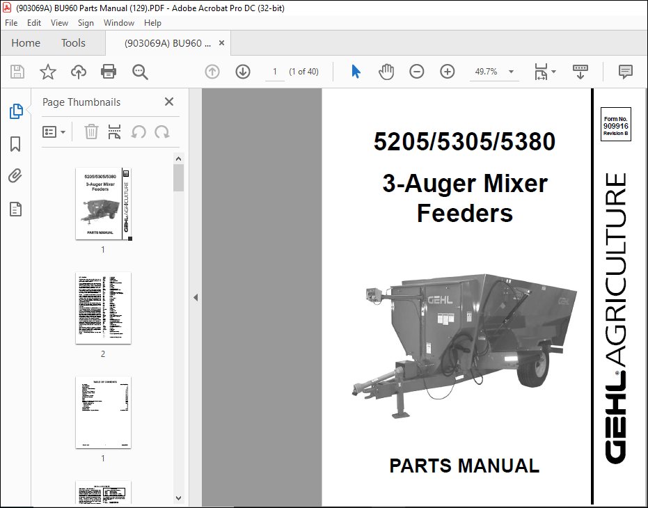
Gehl 5205 5305 5380 3-Auger Mixer Feeders Parts Manual(909916) – PDF DOWNLOAD
Gehl 5205 5305 5380 3-Auger Mixer Feeders Parts Manual(909916) – PDF DOWNLOAD
FILE DETAILS:
Gehl 5205 5305 5380 3-Auger Mixer Feeders Parts Manual(909916) – PDF DOWNLOAD
Language : English
Pages : 40
Downloadable : Yes
File Type : PDF
Size: 1.77 MB
TABLE OF CONTENTS:
Gehl 5205 5305 5380 3-Auger Mixer Feeders Parts Manual(909916) – PDF DOWNLOAD
Introduction Inside Front Cover
Table of Contents 1
Decal Locations 2-7
Auger, Stub Shafts & Bearings 8-9
Front Drive 10-11
Subframe, Doors & Weighbars 12-13
Trailer Frame, Tires & Wheels 14-15
PTO Shaft 16-17
Auger Discharge Assembly 18-19
Belt Discharge Assembly 20-21
Scales 22-23
Lights 24-25
Bumper, Fender, Flood Light & Side Extensions 26-27
Accessories – Safety Chain 28-31
Hydraulic Height Control 28-29
Pressure Relief Kit 30
Safety Chain 31
Alphabetical Index 32
Numerical Index 33-36
Standard Hardware Torque specifications Inside Back Cover
DESCRIPTION:
Gehl 5205 5305 5380 3-Auger Mixer Feeders Parts Manual(909916) – PDF DOWNLOAD
Introduction
- When ordering service parts, specify the correct part number, full description, quantity required, the unit model number and serial number. The Mixer Feeder model and serial number is on a plate located on the left side of the main frame.
- “Right” and “left” are determined from a position standing behind the Mixer Feeder facing the direction of travel. From this position, the discharge gate is on the “left” side. GEHL Company reserves the right to make changes or improvements in the design or construction of any part of the unit without incurring the obligation to install such changes on any previously delivered units
- Refer to the abbreviations table located on this page for the various fastener descriptions. Standard attaching hardware torque values are also provided on the inside back cover. In the exploded view parts list, reference numbers may have additional information following the reference number.
- A tear drop symbol will indicate an application of a “wet” product such as oil, and the number inside the tear drop will correspond to the description in the parts list. Also, a number inside of a hexagon will be the torque value required, in foot pounds, on the associated reference number.
- Items shown in the parts list that do not have reference numbers are shown for reference purposes only and are NOT available for purchase. An indent/bullet system of parts listing is used in this book to indicate parts included in an assembly or subassembly.
- All assembly parts are listed under that assembly and are indented and bulleted. All assembly parts will be included if an assembly or subassembly is ordered. Unless otherwise specified, all cap screws or bolts are Grade 5, cadmium or zinc plated; hexagon nuts for Grade 5 screws or bolts are Grade B; hexagon nuts for other screws or bolts are Grade A.
IMAGES PREVIEW OF THE MANUAL:
More products