$36
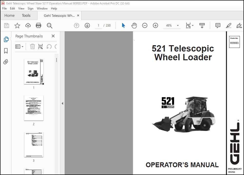
Gehl 521 Telescopic Wheel Loader Operator’s Manual(909883) – PDF DOWNLOAD
Gehl 521 Telescopic Wheel Loader Operator’s Manual(909883) – PDF DOWNLOAD
IMAGES PREVIEW OF THE MANUAL:
DESCRIPTION:
Gehl 521 Telescopic Wheel Loader Operator’s Manual(909883) – PDF DOWNLOAD
Introduction 1
1.1 Notes on this operation manual
- This operation manual contains important information on how to work safely, correctly and economically with the wheel loader model 521T. Therefore, it aims not only at new operators, but is also a reference for experienced ones. It helps to avoid dangerous situations, and reduce repair costs and downtimes. Furthermore, the reliability and the service life of the vehicle will be increased by following the instructions in the operation manual. This is why the operation manual must always be kept at hand in the vehicle.
- Your own safety, as well as the safety of others, depends to a great extent on how the vehicle is moved and operated. Therefore, carefully read and understand this operation manual prior to the first drive.
- This operation manual will help to familiarise yourself more easily with the vehicle, thereby enabling you to use it more safely and efficiently. General safety instructions are given in Section 2 of this operation manual. Carefully read and understand them prior to the first drive. As a rule, keep the following in mind:
Prudent and careful work is the best protection against accidents!
- Special safety instructions with direct reference to service, function and operation of the vehicle are given right before the procedure to follow in the respective sections.
- These safety instructions must always be observed and followed. Operational safety and readiness of the vehicle do not only depend on your skill, but also on maintenance and service of the vehicle. This is why regular maintenance and service work is absolutely necessary.
- Extensive maintenance and repair work must always be carried out by an expert with appropriate training. Insist on using original spare parts when performing maintenance and repair work. This ensures operational safety and readiness of your vehicle, and maintains its value. Your dealer will be pleased to answer any further questions regarding the vehicle or the operation manual.
TABLE OF CONTENTS:
Gehl 521 Telescopic Wheel Loader Operator’s Manual(909883) – PDF DOWNLOAD
Introduction
Introduction 1-1
Notes on this operation manual 1-1
Vehicle overview 1-2
Brief description 1-3
Fields of application 1-4
Regulations 1-5
Vehicle data 1-6
Page left intentionally blank 1-7
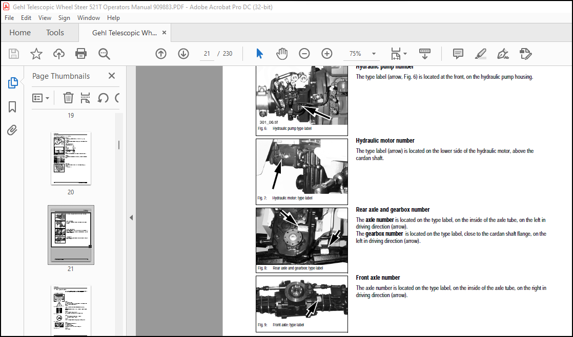
Type labels and component numbers 1-8
Other signs and symbols 1-10
Safety instructions
Safety instructions 2-1
Identification of warnings and dangers 2-1
Designated use and exemption from liability 2-2
General conduct and safety instructions 2-3
Safety instructions regarding operation 2-6
Safety instructions for maintenance 2-10
Warning of special hazards 2-12
Operation
Operation 3-1
Overview of cab 3-2
Overview of switches, levers and consoles 3-4
Taking into service 3-6
Safety instructions 3-6
Taking the vehicle into service for the first time 3-6
Checklists 3-7
Driving the vehicle 3-9
Overview of control elements 3-9
Telltales: overview 3-15
Before starting the engine 3-19
Start the engine 3-19
Jump-starting the vehicle 3-22
Before moving off 3-23
Moving off 3-27
Gear shift 3-28
Changing direction 3-30
Load stabiliser 3-31
Differential lock 3-32
Steering 3-33
Stopping the vehicle 3-35
Parking the vehicle 3-35
Light system 3-36
Signalling system 3-38
Cab heating and ventilation 3-39
Auxiliary heating (option) 3-41
Washer system 3-42
Seat adjustment 3-43
Seat belt 3-45
Vehicle doors 3-47
Other controls 3-48
Towing the vehicle 3-49
Handling the vehicle with a crane 3-50
Loading and transporting the vehicle 3-51
Working with the vehicle 3-53
General safety instructions 3-53
Load diagram 3-53
Safe load indicator 3-55
Overview – control valve of the loader unit on
vehicles WITHOUT “3rd electrically operated control circuit” 3-57
Overview – control valve of the loader unit on
vehicles WITH “3rd electrically operated control circuit” 3-62
Lowering the loader unit with the engine switched off 3-69
Depressurising the quick couplers on the loader unit 3-70
Connecting pressurised quick couplers 3-71
Re-equipping the loader unit 3-73
Connection of electrically driven implements (option) 3-76
Safety feature “Hose burst valve” 3-78
Working with standard bucket and pallet forks 3-80
Troubleshooting
Troubleshooting 4-1
Engine trouble 4-2
Maintenance
Maintenance 5-1
Introduction 5-1
BA 312 01 US-Gehl – Edition 10 * 31201bus-Gehl10IVZfm I-3
Table of contents
Fuel system 5-1
Specific safety instructions 5-1
Refuelling 5-2
Cleaning the fuel tank 5-3
Changing the fuel filter 5-4
Clean the screen filter of the fuel pump 5-5
Changing the leak oil line 5-6
Engine lubrication system 5-7
Check the oil level 5-7
Filling in engine oil 5-8
Changing the engine oil 5-9
Changing the engine oil filter cartridge 5-10
Engine and hydraulics cooling system 5-11
Specific safety instructions 5-11
Engine oil cooler 5-11
Hydraulic oil cooler 5-12
Air filter 5-13
V-belt 5-16
Hydraulic system 5-17
Specific safety instructions 5-17
Hydraulic oil level 5-18
Hydraulic oil reflux filter 5-22
Changing the breather filter 5-23
Hydraulic pressure lines 5-24
Gearboxes and axles 5-25
Rear axle gearbox 5-26
Rear axle differential 5-28
Front axle differential 5-29
Front and rear axle planetary drives 5-30
Lubricating planetary drive bearings 5-31
Lubricating the rear axle oscillation-type bearing 5-31
Telescopic unit and loader unit 5-32
Lubricating the pivots on the loader unit 5-32
Lubricating the telescopic unit 5-32
Adjusting the wear pads 5-33
Tyre care 5-34
Inspection work 5-34
Wheel change 5-35
Heating 5-36
Cleaning the dust filter of the heating system 5-36
Electrical system 5-37
Specific safety instructions 5-37
Service and maintenance work at regular intervals 5-38
Instructions concerning specific components 5-38
General maintenance work 5-40
Cleaning 5-40
Screw connections 5-42
Pivots and hinges 5-42
Engine fluids and lubricants 5-43
Service kits 5-44
Proofs of maintenance 5-45
Maintenance plan (overview) 5-49
Maintenance label 5-52
Helpful information for using the spare parts list
Helpful information for using the spare parts list 6-1
Introduction 6-1
I-4 BA 312 01 US-Gehl -Edition 10 * 31201bus-Gehl10IVZfm
Table of contents
Composition of spare parts list 6-1
Groups 6-1
Group overview 6-2
Figures 6-3
Number index 6-3
Symbols and abbreviations 6-4
Description of symbols 6-4
Abbreviations 6-6
Vehicle data 6-7
Helpful information for ordering spare parts 6-7
Order information 6-8
Address for your spare part order 6-8
Specifications
Specifications 7-1
Frame 7-1
Engine 7-1
Power train 7-2
Axles 7-3
Brakes 7-3
Steering 7-4
Work hydraulics 7-4
Pilot control 7-4
Loader unit 7-5
Weights 7-5
Electrical system 7-6
Tyres 7-9
Noise levels 7-10
Vibration 7-10
Dimensions 7-11
Coolant compound table 7-11
Tightening moments 7-12
General tightening torques 7-12
Specific tightening torques 7-12
Annex
Hydraulics diagram (option) A-1
Hydraulics diagram A-2
Legend – wiring diagram A-4
Wiring diagram A-7
Wiring diagram – option A-8
BA 312 01 US-Gehl – Edition 10 * 31201bus-Gehl10SIXfm I-5
Index
Index
A
Abbreviations 1-1
Air filter cartridge 5-13, 5-15
Auxiliary heating (option) 3-41
B
Backup warning system (option) 3-30
Battery master switch 3-48
Biodegradable oil 5-21
Biodiesel 5-3
Brake/inching pedal 3-11, 3-12
C
Capacities 5-43
CE identification 1-11
Checklists 3-7
Control lever
Continuous operation of implements 3-60, 3-66
For implements and 3rd control circuit 3-60, 3-66
For lift and tilt ram 3-57, 3-62
Securing for driving on public roads 3-61, 3-67
Controls 3-9
D
Designated use and exemption from liability 2-2
Differential lock 3-32
Documents 1-5
Drive pedal 3-10
Driver’s door 3-47
Driving licence 1-5
Driving on public roads 3-23
Driving the vehicle 3-9
Dust filter 5-36
E
Electrical diagram A-7, A-8
Engine fluids 5-43
F
Fields of application
Possible implements 1-4
Fine dust filter (option) 5-36
Front window heater (option) 3-40
Fuel level indicator 3-18
Fuel preheater (option) 3-21
Fuel system
Clean the screen filter of the fuel pump 5-6
G
General conduct 2-3
H
Hazard warning system 3-38
Heating 3-39
L
Legal regulations 1-5
Light system 3-36
Load diagram 1-12, 3-53
Load stabiliser 3-31
Loader unit
Checking the tilt position of the bucket 3-80
Checking the transport position of the bucket 3-80
Depressurising on quick couplers 3-70
Lowering with the engine switched off 3-69
Lubricating 5-32
Re-equipping 3-73
Loading vehicles 3-86
Low speed control (option) 3-12
Lowering the loader unit with the engine switched off 3-69
Lubricants 5-43
M
Maintenance
Air filter 5-13
Biodegradable oil 5-21
Changing the engine oil 5-9
Changing the engine oil filter cartridge 5-10
Changing the filler and breather filter on the hydraulic oil tank 5-23
Changing the fuel filter 5-4
Changing the hydraulic oil 5-19
Checking the engine oil level 5-7
Checking the hydraulic oil level 5-18
Clean the screen filter of the fuel pump 5-5
Cleaning 5-40
Cleaning the engine oil cooler 5-11
Cleaning the fuel tank 5-3
Cleaning the hydraulic oil cooler 5-12
Electrical diagram A-8
Electrical system 5-37
Engine and hydraulics cooling system 5-11
Engine lubrication system 5-7
Filling in engine oil 5-8
Front axle differential 5-29
Fuel system 5-1
Gearboxes and axles 5-25
General maintenance work 5-40
Heating 5-36
Hydraulic oil reflux filter 5-22
Hydraulic pressure lines 5-24
Hydraulic system 5-17
Instructions concerning specific components 5-38
Lubricating the loader unit 5-32
Lubricating the oscillation-type bearing 5-31
Maintenance plan 5-49
Pivots and hinges 5-42
Planetary drives 5-30
Proofs of maintenance 5-45
Rear axle differential 5-28
Rear axle gearbox 5-26
Screw connections 5-42
Service and maintenance work at regular intervals 5-38
Telescopic unit 5-32
Topping up the hydraulic oil 5-18
Tyre care 5-34
V-belt 5-16
Wheel change 5-35
Manual throttle 3-11
Manual throttle lever 3-11
Maximum speed 1-11
Multifunctional lever 3-13
Index
I
I-6 BA 312 01 US-Gehl – Edition 10 * 31201bus-Gehl10SIXfm
Index
N
Noise level 1-10, 7-10
O
Oil preheating (option) 3-21
Operation 3-1
Backup warning system (option) 3-30
Before moving off 3-23
Before starting the engine 3-19
Changing direction 3-30
Drive ranges 3-28
Moving off 3-27
Overview of cab 3-2
Overview of control elements 3-9
Overview of instrument panel, multifunctional lever
and drive switch 3-4
Parking the vehicle 3-35
Restrictor unit on tilt ram (option) 3-78
Seat belt height setting 3-45
Selecting the drive range 3-28
Start the engine 3-19
Stopping the vehicle 3-35
Telescopic unit 3-58
Telescopic unit (option) 3-64
Operation manual
Important 1-1
P
Pallet forks 3-87
Approaching the material 3-87
Loading the material 3-88
Safety instructions 3-87
Setting down the material 3-90
Parking brake 3-12
Picking up an implement 3-73
PME fuel 5-3
Preheating start switch 3-9
R
Re-equipping the loader unit 3-73
Refuelling 5-2
Rotating beacon (option) 3-38
Running-in period 3-6
S
Safe load indicator 3-55
Safe work load 3-55
Safety instructions 2-1
Identification 2-1
Operating 2-6
Special hazards 2-12
Seat adjustment 3-43
Armrest setting 3-44
Backrest adjustment 3-44
Height setting 3-43
Longitudinal setting 3-44
Weight adjustment 3-43
Seat belt height setting 3-45
Service brake 3-26
Service kits 5-44
Signalling system 3-38
Signs and symbols 1-10
Specifications 7-1
Axles 7-3
Brakes 7-3
Coolant compound table 7-11
Dimensions 7-11
Electrical system 7-6
Engine 7-1
Frame 7-1
Loader unit 7-5
Noise levels 7-10
Pilot control 7-4
Power train 7-2
Steering 7-4
Tightening moments 7-12
Tyres 7-9
Vibration 7-10
Weights 7-5
Work hydraulics 7-4
Starting aid 3-22
Starting with starting aid 3-30
Steering 3-25
Steering angle limit 7-9
Steering-column control lever 3-9
Symbols 1-1
T
Taking into service 3-6
Checklists 3-7
Safety instructions 3-6
Taking the vehicle into service for the first time 3-6
Telescopic unit
Extend/raise 3-58
Extending/raising (option) 3-64
Lubricating 5-32
Retracting/lowering 3-59, 3-65
Telltales 3-15
The 1-5
Tip switch on control lever 3-57
Tip switch on control lever (option) 3-63
Towing the vehicle 3-49
Transport 3-81
Turn indicators 3-38
Type labels and component numbers 1-8
Tyre care 5-34
V
VBG 40 §50 1-5
Vehicle
Brief description 1-3
Crane handling 3-50
Data 1-6
Fields of application 1-4
Loading and transporting 3-51
Overview 1-2
Vehicle equipment 1-5
Vehicle inspections 1-5
Vehicle warning identification 1-6
Ventilation 3-39
Ventilation, fresh air 3-39
W
Washer pump 3-42
BA 312 01 US-Gehl – Edition 10 * 31201bus-Gehl10SIXfm I-7
Index
Washer system 3-42
Tank 3-42
Wheel change 5-35
Wheel synchronisation position 3-25
Window wiper 3-42
Wiring diagram A-7
Working
with pallet forks 3-87
with standard bucket 3-80
with the vehicle 3-53
Approaching the material 3-87
Freeing the vehicle 3-86
General safety instructions 3-53
Grading 3-85
Loading heaped material 3-85
Loading loose material 3-82
Loading the material 3-88
Practical hints 3-86
Removing material/digging in hard soil 3-84
Removing material/digging in soft soil 3-83
Safe load indicator 3-55
Safety feature “Hose burst valve” (option) 3-78
Setting down the material 3-90
More products