$31
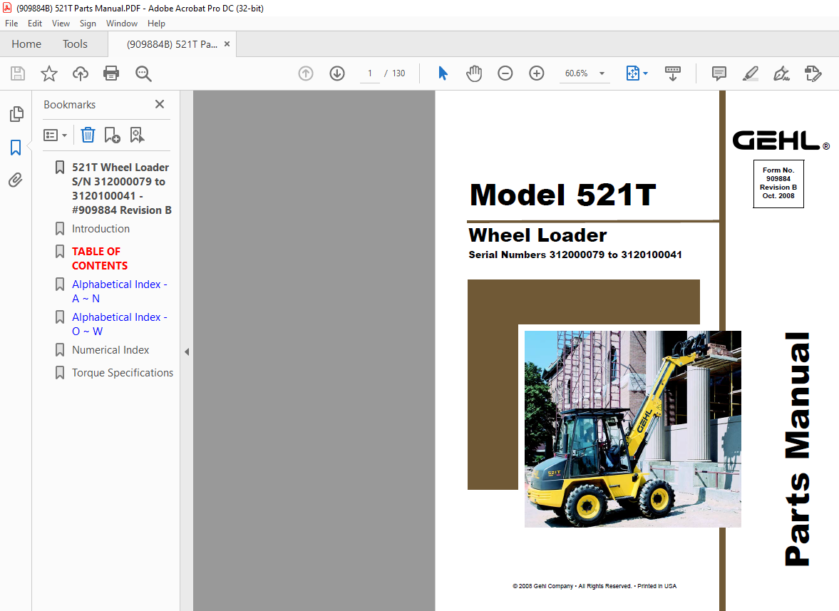
Gehl 521T Wheel Loader Parts Manual 909884 – PDF DOWNLOAD
Gehl 521T Wheel Loader Parts Manual 909884 – PDF DOWNLOAD
FILE DETAILS:
Gehl 521T Wheel Loader Parts Manual 909884 – PDF DOWNLOAD
Language : English
Pages : 130
Downloadable : Yes
File Type : PDF
Size: 4.42 MB
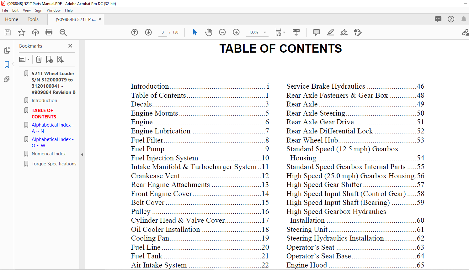
TABLE OF CONTENTS:
Gehl 521T Wheel Loader Parts Manual 909884 – PDF DOWNLOAD
Introduction i
Table of Contents 1
Decals 3
Engine Mounts 5
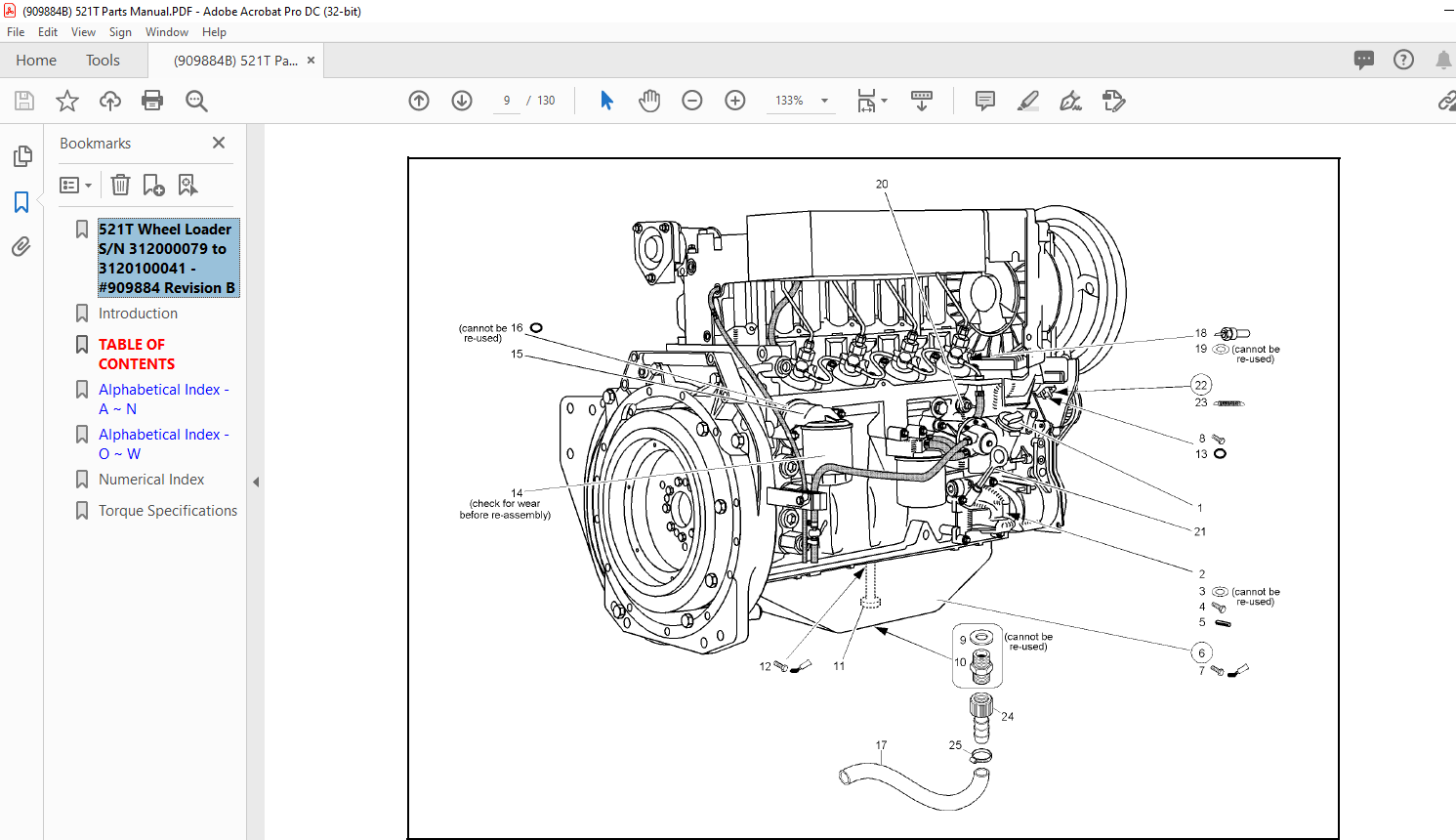
Engine 6
Engine Lubrication 7
Fuel Filter 8
Fuel Pump 9
Fuel Injection System 10
Intake Manifold & Turbocharger System 11
Crankcase Vent 12
Rear Engine Attachments 13
Front Engine Cover 14
Belt Cover 15
Pulley 16
Cylinder Head & Valve Cover 17
Oil Cooler Installation 18
Cooling Fan 19
Fuel Line 20
Fuel Tank 21
Air Intake System 22
Throttle Pedal 23
Hand Throttle 24
Frame/Counterweight 25
Variable Displacement Pump Installation 26
Drive Hydraulics Installation 27
Drive Pilot Installation 28
Hydraulic Motor Oil Cooler 29
Hydraulic Motor Oil Cooler Installation 30
Variable Displacement Pump 32
Inching Valve 33
Variable Displacement Motor 34
Low Speed Control 35
Wheels and Tires 36
Front Axle 37
Front Axle Steering 38
Front Axle Gear Drive 39
Front Axle Differential 40
Front Axle Differential Lock 41
Brake 42
Front Wheel Hub 43
Front Axle Differential Lock Hydraulics 44
Parking Brake 45
Service Brake Hydraulics 46
Rear Axle Fasteners & Gear Box 48
Rear Axle 49
Rear Axle Steering 50
Rear Axle Gear Drive 51
Rear Axle Differential Lock 52
Rear Wheel Hub 53
Standard Speed (12 5 mph) Gearbox
Housing 54
Standard Speed Gearbox Internal Parts 55
High Speed (25 0 mph) Gearbox Housing 56
High Speed Gear Shifter 57
High Speed Input Shaft (Control Gear) 58
High Speed Input Shaft (Bearing) 59
High Speed Gearbox Hydraulics
Installation 60
Steering Unit 61
Steering Hydraulics Installation 62
Operator’s Seat 63
Operator’s Seat Base 64
Engine Hood 65
Cowl & Lower Body Trim 66
Exhaust System 67
Instrument Panel 68
Vehicle Lighting 69
Main Wiring Harness 70
Battery 72
Window Wipers 73
Cab Wiring Harness/Instrument Panel 74
Cab Wiring Harness/Front Components 75
Cab Wiring Harness/Fuse Box 76
Cab Wiring Harness/Rear Components 77
Cab Wiring Harness 78
Cab 79
Cab Doors 80
Cab Interior Cover Trim 81
Cab Mats & Filters 82
Cab Heater 83
Cab Protection Screens 84
Hydraulic Oil Circulating System 85
Hydraulic System Control Valve 86
Hydraulic Oil Tank 87
Pilot Valve 88
TABLE OF CONTENTS
909884/BP1008 2 Printed in U S A
Pilot Valve Installation 89
Electrical Control Circuit 90
Safe Load Indicator 91
Telescoping Boom 92
Boom Frame Trim 94
Quickhitch Assembly 95
Load Stabilizer 96
Lift Cylinder 97
Tilt Cylinder 98
Self-Leveling Cylinder 99
Extension Cylinder 100
Cylinders Installation 101
Bucket 102
Pallet Forks 103
Numerical Index 107
DESCRIPTION:
Gehl 521T Wheel Loader Parts Manual 909884 – PDF DOWNLOAD
Serial Numbers 312000079 to 3120100041
INTRODUCTION:
When ordering service parts, specify the correct part number, full description, quantity required, the unit model number and serial number. For your safety and continued proper operation, use only genuine GEHL service parts. The model and serial number for this unit are on a tag located on a panel on the front of the cab.
- ”Right” and ”left” are determined from a position sitting on the seat and facing forward. MANITOU AMERICAS, INC. reserves the right to make changes or improvements in the design or construction of any part of the unit without incurring the obligation to install such changes on any previously delivered units.
- Refer to the abbreviations table located on this page for the various fastener descriptions. Standard attaching hardware torque values are also provided on the inside back cover. Metric torque values shown in the illustrations are in Newtonmeters and can be converted to foot-pounds by multiplying by 0.738.
- Specific Reference Numbers, indicating a complete assembly, are circled in some illustrations. A small bag, pictured in some illustrations, indicates a seal kit (seals, o-rings, etc.). In the exploded view parts list, additional information may follow the Reference Number.
Serial number breaks are indicated as follows:
• (SN 999 and before) – indicates serial numbers
up to and including 999.
• (SN 1000 – 2000) – indicates serial numbers
between 1000 and 2000.
• (SN 999 and up) – indicates serial numbers
including 999 and after.
Serial number exceptions and inclusion are
indicated as follows:
• (SN 999 and before except 997) – indicates
serial numbers up to and including 999,
EXCEPT 997.
• (SN 1000 – 2000 except 1996 including 997) –
indicates serial numbers between 1000 and
2000, INCLUDING 997 EXCEPT 1996.
• (SN 2001 and up including 1996) – indicates
serial numbers including 2001 and after,
INCLUDING 1996.
Unless otherwise specified, all cap screws and
bolts are Grade 8.8, cadmium or zinc plated.
IMAGES PREVIEW OF THE MANUAL:
More products