$34
Gehl 5625 Skid Loader Shop Manual 907245 – PDF DOWNLOAD
Gehl 5625 Skid Loader Shop Manual 907245 – PDF DOWNLOAD
FILE DETAILS:
Gehl 5625 Skid Loader Shop Manual 907245 – PDF DOWNLOAD
Language : English
Pages : 296
Downloadable : Yes
File Type : PDF
Size: 40.3 MB
IMAGES PREVIEW OF THE MANUAL:
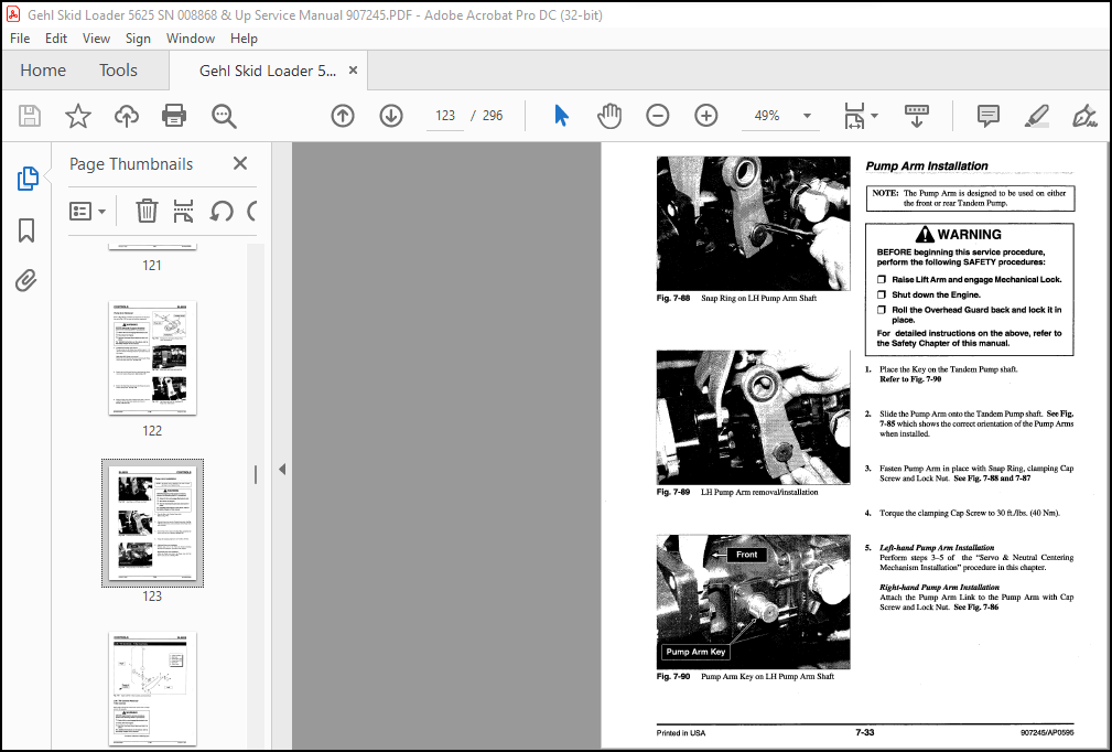
TABLE OF CONTENTS:
Gehl 5625 Skid Loader Shop Manual 907245 – PDF DOWNLOAD
Specifications 1
General Information ……………………………………………………………………………………………………………………….. 1-1
Standard Features …………………………………………………………………………………………………………………………… 1-l
Tire Options ………………………………………………………………………………………………………………………………….. 1-1
Buckets & Capacities ……………………………………………………………………………………………………………………… 1-1
Dimensions …………………………………………………………………………………………………………………………………… 1-2
Safety 2
General lnformation ……………………………………………………………………………………………………………………….. 2-1
Signal Words ………………………………………………………………………………………………………………………………… 2-1
Additional Safety Reminders …………………………………………………………………………………………………………… 2-1
Mandatory Safety Shutdown Procedure ……………………………………………………………………………………………. 2-2
Lift Cylinder Mechanical Lock ……………………………………………………………………………………………………….. 2-3
Cylinder Lock Engagement …………………………………………………………………………………………………………….. 2-3
Cylinder Lock Disengagement ………………………………………………………………………………………………………… 2-4
Overhead Guard – Raising ……………………………………………………………………. ‘. ……………………………………….. 2-5
Overhead Guard – Lowering ……………………………………………………………………………………………………………. 2-6
Relieving Hydraulic Pressure ………………………………………………………………………………………………………….. 2-6
Loader Raising Procedure ………………………………………………………………………………………………………………. 2-7
Loader Lowering Procedure …………………………………………………………………………………………………………….. 2-7
Safety Decal Locations …………………………………………………………………………………………………………………… 2-8
Decals 3
New Decal Application …………………………………………………………………………………………………………………… 3-l
Paint Finish …………………………………………………………………………………………………………………………………… 3-1
Decal List ……………………………………………………………………………………………………………………………………… 3-2
Lubrication 4
General Information ……………………………………………………………………………………………………………………….. 4-1
Printed in USA 907245/AP0595
Table of Contents SL5625
Hydraulic Oil Reservoir …………………………………… -……………………………………………………………………………. 4-1
Crankcase Oil ……………………………………………………………………………………………………………………………….. 4-1
Chaincases ……………………………………………………………………………………………………………………………………. 4-2
Planetary Gearcase Oil …………………………………………………………………………………………………………………… 4-2
Grease Fitting Locations ………………………………………………………………………………………………………………… 4-3
Chassis 5
Introduction ………………………………………………………………………………………………………………………………….. 5-1
Engine Access Cover Removal ……………………………………………………………………………………………………….. 5-2
Engine Access Cover Installation ……………………………………………………………………………………………………. 5-2
Overhead Guard Removal ………………………………………………………………………………………………………………. 5-3
Overhead Guard Installation …………………………………………………………………………………………………………… 5-5
Seat Removal ………………………………………………………………………………………………………………………………… 5-6
Seat Installation …………………………………………………………………………………………………………………………….. 5-7
Restraint Bar Removal …………………………………………………………………………………………………………………… 5-8
Restraint Bar Installation ………………………………………………………………………………………………………………… 5-8
Quick-Tach Removal …………………………………………………………………………………………………………………… 5-10
Quick-Tach Installation ………………………………………………………………………………………………………………… 5-11 )
Lift Arm Removal/ Disassembly ……………………………… , …………………………………………………………………. 5-12
Lift Arm Installation/ Assembly ……………………………………….•…………………………………………………………. 5-16
Lift Arm Bushing Replacement …………………………………………………………………………………………………….. 5-18
Lift Arm Stop Installation/ Adjustment …………………………………………………………………………………………. 5-20
T-Bar Cover Removal ………………………………………………………………………………………………………………….. 5-22
T-Bar Cover Installation ……………………………………………………………………………………………………………….. 5-22
Floor Cover Removal …………………………………………………………………………………………………………………… 5-23
Floor Cover Installation ……………………………………………………………………………………………………………….. 5-24
Bottom Cover Removal ………………………………………………………………………………………………………………… 5-25
Bottom Cover Installation …………………………………………………………………………………………………………….. 5-25
Fuel Tank Removal ……………………………………………………………………………………………………………………… 5-26
Fuel Tank Installation …………………………………………………………………………………………………….. -……………. 5-27
Fuel Level Sender Removal ………………………………………………………………………………………………………….. 5-28
Fuel Level Sender Installation ……………………………………………………………………………………………………….. 5-28
Rear Grill Removal ……………………………………………………………………………………………………………………… 5-29
Rear Grill Installation …………………………………………………………………………………………………………………… 5-29
907245/ AP0595 ii Printed in USA
SL5625 Table of Contents
Drive 6
Introduction …………………………………………………………………………………………………………………………………… 6-1
Drive Chain Adjustinent ………………………………………………………………………………………………………………… 6-2
Drive Chain Removal …………………………………………………………………………………………………………………….. 6-4
Drive Chain Installation …………………………………………………………………………………………………………………. 6-5
Axle & Sprocket Removal ………………………………………………………………………………………………………………. 6-6
Axle & Sprocket Installation …………………………………………………………………………………………………………… 6-7
Axle & Wheel Bearing Disassembly ………………………………………………………………………………………………… 6-8
Axle & Wheel Bearing Assembly ……………………………………………………………………………………………………. 6-9
Idler Sprocket & Bearing Removal ………………………………………………………………………………………………… 6-10
Idler Sprocket & Bearing Reassembly and Installation …………………………………………………………………….. 6-12
Planetary Gearcase Removal …………………………………………………………………………………………………………. 6-14
Planetary Gearcase Installation ……………………………………………………………………………………………………… 6-17
Planetary Gearcase Disassembly ……………………………………………………………………………………………………. 6-20
Planetary Gearcase Assembly ……………………………………………………………………………………………………….. 6-23
Controls 7
Introduction …………………………………………………………………………………………………………………………………… 7-1
T-BarRemoval ……………………………………………………………………………………………………………………………… 7-2
T-Bar Installation …………………………………………………………………………………………………………………………… 7-3
T-Bar Position Adjustinent ……………………………………………………………………………………………………………… 7-4
T-Bar Tracking Adjustment, Traction Controls ………………………………………………………………………………. : .. 7-6
Left T-Bar Assembly, T-Bar Controls ……………………………………………………………………………………………… 7-8
Left T-Bar Assembly, Hand / Foot Controls ……………………………………………………………………………………. 7-11
Right T-Bar Assembly ………………………………………………………… ; ………………………………………………………. 7-13
Crosstube Removal, T-Bar Controls ………..•……………………………………………………………………………………. 7-17
Crosstube Installation, T-Bar Controls ……………………………………………………………………………………………. 7-18
Crosstube Removal, Hand/ Foot Controls ………………………………………………………………………………………. 7-21
Cross tube Installation, Hand / Foot Controls …………………………………………………………………………………… 7-23
Servo & Neutral Centering Mechanism Removal …………………………………………………………………………….. 7-25
Servo & Neutral Centering Mechanism Installation …………………………………………………………………………. 7-27
Neutral Centering Adjustinent. ………………………………………………………………………………………………………. 7-30
Pump Arm Removal …………………………………………………………………………………………………………………….. 7-32
Printed in USA iii 907245/AP0595
Table of Contents SL5625
Pump Arm Installation …………………………………………………………………………………………………………………. 7-33
Lift/ Tilt Control Removal, T-Bar Controls …………………………………………………………………………………… 7-34
Lift/ Tilt Control Installation, T-Bar Controls ………………………………………………………………………………… 7-35
Lift/ Tilt Control Adjustment, T-Bar Controls ……………………………………………………………………………….. 7-35
Lift/ Tilt Control Removal, Hand/Foot Controls …………………………………………………………………………….. 7-37
Lift /Tilt Control Installation, Hand/ Foot Controls ……………………………………………………………………….. 7-38
Lift/ Tilt Control Adjustment, Hand/ Foot Controls ………………………………………………………………………. 7-39
Auxiliary Hydraulics Cable Removal, T-Bar Controls …………………………………………………………………….. 7-41
Auxiliary Hydraulics Cable Installation, T-Bar Controls …………………………………………………………………. 7-42
Auxiliary Hydraulics Cable Adjustment, T-Bar Controls …………………………………………………………………. 7-43
Auxiliary Hydraulics Rod Removal, Hand/Foot Controls ………………………………………………………………… 7-44
Auxiliary Hydraulics Rod Installation, Hand/Foot Controls …………………………………………………………….. 7-45
Auxiliary Hydraulics Rod Adjustment, Hand/ Foot Controls …………………………………………………………… 7-46
Throttle Installation ……………………………………………………………………………………………………………………… 7-48
Hand Throttle Adjustment ……………………………………………………………………………………………………………. 7-50
Throttle Tension Adjustment ………………………………………………………………………………………………………… 7-51
Foot Throttle Adjustment. …………………………………………………………………………………………………………….. 7-52
Parking Brake Adjustment …………………………………………………………………………………………………………… 7-54
Parking Brake Pad Replacement. …………………………………………………………………………………………………… 7-55
Hydrostatic System 8
Introduction ………………………………………………………………………………………………………………………………….. 8-1
Troubleshooting Guide ………………………………………………………………………………………………………………….. 8-2
Case Drain Test …………………………………………………………………………………………………………………………….. 8-6
Charge Pressure Test & Adjustment ……………………………………………………………………………………………….. 8-8
Tandem Pump Relief Valves ………………………………………………………………………………………………………… 8-1 O
Tandem Pump Removal ……………………………………………………………………………………………………………….. 8-11
Tandem Pump Installation ……………………………………………………………………………………………………………. 8-18
Pump Drive Coupling Removal …………………………………………………………………………………………………….. 8-22
Pump Drive Coupling Installation …………………………………………………………………………………………………. 8-23
Drive Motor Removal .. : ……………………………………………………………………………………………………………….. 8-25
Drive Motor Installation …………………………………………….. : ………………………………………………………………. 8-26
907245/ AP0595 iv Printed in USA
SL5625 Table of Contents
Hydraulic Oil Cooler Removal ………………………………………………………………………………………………………. 8-28
Hydraulic Oil Cooler Installation …………………………………………………………………………………………………… 8-29
Hydraulic System 9
Introduction …………………………………………………………………………………………………………………………………… 9-1
Troubleshooting Guide …………………………………………………………………………………………………………………… 9-2
Relief Pressure Test, Control Valve …………………………………………………………………………………………………. 9-6
Tilt Cylinder Test …………………………………………………………………………………………………………………………… 9-8
Self-Leveling Valve Test ………………………………………………………………………………………………………………. 9-10
Lift Cylinder Test ………………………………………………………………………………………………………………………… 9-l 1
Solenoid Valve Test. …………………………………………………………………………………………………………………….. 9-13
Hydraulic Oil Filter Element Replacement …………………………………………………………………………………….. 9-16
Case Drain Oil Filter Element Replacement ……………………………………………………………………………………. 9-17
Hydraulic Oil Strainer, Removal and Cleaning ………………………………………………………………………………… 9-18
Tilt Cylinder Removal ………………………………………………………………………………………………………………….. 9-21
Tilt Cylinder Installation …………………………………… : ………………………………………………………………………… 9-22
Lift Cylinder Removal ………………………………………………………………………………………………………………….. 9-24
Lift Cylinder Installation ………………………………………………………………………………………………………………. 9-25
Lift/ Tilt Cylinder Disassembly …………………………………………………………………………………………………….. 9-26
Lift/ Tilt Cylinder Assembly ·····························.···························································································9-28
Gear Pump Removal ……………………………………………………………………………………. , ……………………………… 9-29
Gear Pump Installation …………………………………………………………………………………………………………………. 9-30
Self-Leveling Valve Removal ……………………………………………………………………………………………………….. 9-32
Self-Leveling Valve Installation …………………………………………………………………………………………………….. 9-33
Self-Leveling Valve Adjustment ……………….. : …………………………………………………………………………………. 9-34
Lift/ Tilt Solenoid Valve, Removal & Installation …………………………………………………………………………… 9-36
Lift/ Tilt Solenoid Valve, Disassembly & Reassembly ……………………………………………………………………. 9-37
Control Valve Removal ………………………………………………………………………………………………………………… 9-38
Control Valve Installation …………………………………………………………………………………………………………….. 9-43
High-Flow Manifold Valve, Removal & Installation ……………………………………………………………………….. 9-47
High-Flow Manifold Valve, Disassemly & Reassembly …………………………………………………………………… 9-49
Hydraulic System Schematic, SL5625SX ………………………………………………………………………………………. 9-50
Hydraulic System Schematic, SL5625DX ……………………………………………………………………………………… 9-52
Printed in USA V 907245/AP0595
Table of Contents SL5625
Electrical System 10
Description of Operation ………………………………………………………………………………………………………………. 10-l
Troubleshooting ………………………………………………………………………………………………………………………….. 10-2
QGS Control Module Operation ……………………………………………………………………………………………………. 10-4
QGS Control Module Test ……………………………………………………………………………………………………………. 10-4
Glow Plug Test ……………………………………………………………………………………………………………………………. 10-5
Glow Plug Relay Test ………………………………………………………………………………………………………………….. 10-6
Relay Test …………………………………………………………………………………………………………………………………… 10-7
Water Temperature Switch Test …………………………………………………………………………………………………….. 10-8
Seat Switch, Removal / Installation ……………………………………………………………………………………………….. 10-8
Restraint Bar Switch, Removal/ Installation …………………………………………………………………………………… 10-9
Circuit / Function Chart ……………………………………………………………………………………………………………… 10-11
Wiring Termination, Engine Compartment …………………………………………………………………………………… 10-13
Wiring Harness, Engine Compartment …………………………………………………………………………………………. 10-16
Wiring Termination, Instrument Panel …………………………………………………………………………………………. 10-18
Wiring Harness, Instrument Panel ……………………………………………………………………………………………….. 10-20
Electrical System Schematic ………………………………………………………………………………………………………. 10-22
Engine 11
Introduction ………………………………………………………………………………………………………………………………… 11-1
Troubleshooting Guide …………………………………………………………………………………………………………………. 11-2
Oil Filter Element Removal ………………………………………………………………………………………………………….. 11-4
Oil Filter Element Installation ……………………………………………………………………………………………………….. 11-4
Air Filter Assembly, Removal /Installation ……………………………………………………………………………………. 11-5
Air Filter Element, Removal/ Installation ………………………………………………………………………………………. 11-6
Air Filter Element Cleaning ………………………………………………………………………………………………………….. 11-7
Battery Removal / Installation ………………………………………………………………………………………………………. 11-8
Starter Removal / Installation ………………………………………………………………………………………………………… 11-9
Exhaust Assembly Removal ……………………………………………………………………………………………………….. 11-10
Exhaust Assembly Installation …………………………………………………………………………………………………….. 11-11
Fan Belt Adjustment …………………………………………………………………………………………………………………… 11-12
Radiator Removal ………………………………………………………………………………………………………………………. 11-15
Radiator Installation …………………………………………………………………………………………………………………… 11-18
907245/ AP0595 vi Printed in USA
SL5625 Table of Contents
Fan Shroud Adjustment ………………………………………………………………………………………………………………. 11-20
Engine Removal …………………………………………………………………………………………………………………………. 11-22
Engine Installation …………………………………………………………………………………………………………………….. : 11-27
Index 12
More products