$28
Gehl 6620 Series SL6620 & SL6625 Skid Loader Shop Manual 904167 – PDF DOWNLOAD
Gehl 6620 Series SL6620 & SL6625 Skid Loader Shop Manual 904167 – PDF DOWNLOAD
FILE DETAILS:
Gehl 6620 Series SL6620 & SL6625 Skid Loader Shop Manual 904167 – PDF DOWNLOAD
Language : English
Pages : 114
Downloadable : Yes
File Type : PDF
Size: 10.6 MB
IMAGES PREVIEW OF THE MANUAL:
DESCRIPTION:
Gehl 6620 Series SL6620 & SL6625 Skid Loader Shop Manual 904167 – PDF DOWNLOAD
INTRODUCTION:
This service manual covers the SL6620 and SL6625 Skid Loaders. The latest factory service information has been compiled by our Service and Engineering personnel to give you the best Service Information available. Follow all procedures carefully to avoid unnecessary delays and damage to any part of the Loader.
- Where procedures are given step by step, please follow them in order. The Hydraulic System and the Engine are the two most critical systems of the Skid Loader, from a service standpoint. When any service is performed on the Hydraulic System, always clean the Hydraulic Components and Fittings before disconnecting any Hydraulic Lines, since contamination is the greatest cause of failure.
- For Engine repairs, consult your 200 Series Perkins Workshop Manual. The Model Number and Serial Number are located on a Decal inside the Right Chassis Riser, above the Lift Cylinder Pivot. “Right” and “Left” are determined from position on the Seat facing forward.
- From this position the Traction Control T-bar is on the “Left” and the Lift/Tilt Control T-bar is on the “Right”. The Perkins 4.154 Diesel Engine is used in the SL6620 and SL6625. The Engine Number is stamped on a machined pad on the right side of the Cylinder Block just above the Fuel Injection Pump. A typical Engine Number is GABI2345J.
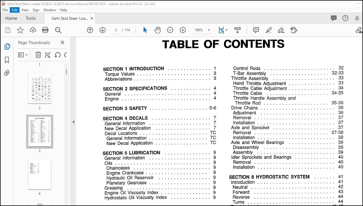
TABLE OF CONTENTS:
Gehl 6620 Series SL6620 & SL6625 Skid Loader Shop Manual 904167 – PDF DOWNLOAD
SECTION 1 INTRODUCTION . . . . . . . . . . . . . . 1
Torque Values . . . . . . . . . . . . . . . . . . . . . . . . 3
Abbreviations . . . . . . . . . . . . . . . . . . . . . . . . . 3
SECTION 2 SPECIFICATIONS . . . . . . . . . . . . . 4
General ………………………. 4
Engine ………………………… 4
SECTION 3 SAFETY . . . . . . . . . . . . . . . . . . . 5-6
SECTION 4 DECALS . . . . . . . . . . . . . . . . . . . 7
General Information . . . . . . . . . . . . . . . . . . . . 7
New Decal Application . . . . . . . . . . . . . . . . . . 7
Decal Locations . . . . . . . . . . . . . . . . . . . . . . 7C
General Information . . . . . . . . . . . . . . . . . . . 7C
New Decal Application . . . . . . . . . . . . . . . . . 7C
SECTION 5 LUBRICATION …………… 9
General Information . . . . . . . . . . . . . . . . . . . . 9
Oils …………………………. 9
Chaincases ……………………. 9
Engine Crankcase . . . . . . . . . . . . . . . . . . . . 9
Hydraulic Oil Reservoir . . . . . . . . . . . . . . . . . 9
Planetary Gearcase . . . . . . . . . . . . . . . . . . . . 9
Greasing ……………………… 9
Engine Oil Viscosity Index . . . . . . . . . . . . . . . . 9
Hydrostatic Oil Viscosity Index . . . . . . . . . . . . . 9
SECTION 6 CHASSIS . . . . . . . . . . . . . . . . . . 11
Description . . . . . . . . . . . . . . . . . . . . . . . . . 11
General Information . . . . . . . . . . . . . . . . . . . 11
Overhead Guard . . . . . . . . . . . . . . . . . . . 11-12
In-Seat Safety Switch-Before S.N. 2651 . . . . . 13
In-Seat Safety Switch-After S.N. 2650 . . . . . . . 13
Seat . . . . . . . . . . . . . . . . . . . . . . . . . . . . . 14
Restraint Bar Switch . . . . . . . . . . . . . . . . . . 15
Lift Arm Assembly . . . . . . . . . . . . . . . . . . 15-17
Attachment Assembly . . . . . . . . . . . . . . . 17-18
Floor Plate . . . . . . . . . . . . . . . . . . . . . . . . i 8
Bottom Covers . . . . . . . . . . . . . . . . . . . . . . 19
Consoles . . . . . . . . . . . . . . . . . . . . . . . . i 9-20
Access Cover . . . . . . . . . . . . . . . . . . . . . . . 20
Fuel Tank . . . . . . . . . . . . . . . . . . . . . . . 20-2i
SECTION 7 DRIVE . . . . . . . . . . . . . . . . . . . . 23
Brakes ………………………. 23
Disc Brake Adjustment . . . . . . . . . . . . . . . . . 23
Brake Pad Replacement . . . . . . . . . . . . . . 23-24
Brake Cables . . . . . . . . . . . . . . . . . . . . . 25-26
Traction Drive T-Bar . . . . . . . . . . . . . . . . . . . 26
Neutral Adjustment . . . . . . . . . . . . . . . . . . . 26
Servo Adjustment . . . . . . . . . . . . . . . . . . . . 27
Take-Up Rods . . . . . . . . . . . . . . . . . . . . . . 28
Control Rods . . . . . . . . . . . . . . . . . . . . . 28-29
Pivot Shaft and Torsion Tube . . . . . . . . . 29-20
T-Bar Assembly ………………. 30-3i
Lift/Tilt T-Bar . . . . . . . . . . . . . . . . . . . . . . . . 31
Control Linkage Adjustment . . . . . . . . . . . 31-32
Control Rods . . . . . . . . . . . . . . . . . . . . . . . 32
T-Bar Assembly . . . . . . . . . . . . . . . . . . . 32-33
Throttle Assembly . . . . . . . . . . . . . . . . . . . . 33
Hand Throttle Adjustment . . . . . . . . . . . . . . . 33
Throttle Cable Adjustment . . . . . . . . . . . . . . . 34
Throttle Cable . . . . . . . . . . . . . . . . . . . . 34<~5
Throttle Handle Assembly and
Throttle Rod . . . . . . . . . . . . . . . . . . . . . 35-36
Drive Chains . . . . . . . . . . . . . . . . . . . . . . . . 36
Adjustment . . . . . . . . . . . . . . . . . . . . . . . . 36
Removal …………………….. 37
Installation . . . . . . . . . . . . . . . . . . . . . . . . . 37
Axle and Sprocket . . . . . . . . . . . . . . . . . . . . 37
Removal . . . . . . . . . . . . . . . . . . . . . . . . 37-38
Installation . . . . . . . . . . . . . . . . . . . . . . . . . 38
Axle and Wheel Bearings . . . . . . . . . . . . . . . 39
Disassembly . . . . . . . . . . . . . . . . . . . . . . . 39
Assembly . . . . . . . . . . . . . . . . . . . . . . . . . 39
Idler Sprockets and Bearings . . . . . . . . . . . . . 40
Removal …………………….. 40
Installation . . . . . . . . . . . . . . . . . . . . . . . . . 40
SECTION 8 HYDROSTATIC SYSTEM ……. 41
Introduction . . . . . . . . . . . . . . . . . . . . . . . . . 41
Neutral ……………………… 42
Forward …………………….. 43
Reverse …………………….. 44
Turns ………………………. 44
Troubleshooting . . . . . . . . . . . . . . . . . . . . 45-47
Hydrostatic Testing . . . . . . . . . . . . . . . . . . . . 48
Drive Motor . . . . . . . . . . . . . . . . . . . . . . . . 48
Charge Pressure . . . . . . . . . . . . . . . . . . . . . 48
Service . . . . . . . . . . . . . . . . . . . . . . . . . . . 48
Tandem Pump ……………….. 48-53
Tandem Pump-Valve Block . . . . . . . . . . . . 54-55
Pump Drive Coupling . . . . . . . . . . . . . . . . . . 55
Hydrostatic Drive Motor . . . . . . . . . . . . . . 56-60
SECTION 9 HYDRAULIC SYSTEM . . . . . . . . . 6i
Introduction . . . . . . . . . . . . . . . . . . . . . . . . . 61
Cylinders . . . . . . . . . . . . . . . . . . . . . . . . . . 62
Hydraulic Hoses and Tubing . . . . . . . . . . . . . 62
Electrical Components . . . . . . . . . . . . . . . . . 62
Troubleshooting . . . . . . . . . . . . . . . . . . . . 63-64
Hydraulic Testing . . . . . . . . . . . . . . . . . . . . . 65
Control Valve Relief Pressure . . . . . . . . . . . . 65
Lift and Tilt System Pump . . . . . . . . . . . . . . 65
Tilt Cylinders . . . . . . . . . . . . . . . . . . . . . . . 65
Lift Cylinders . . . . . . . . . . . . . . . . . . . . . . . 66
Service . . . . . . . . . . . . . . . . . . . . . . . . . . . 66
Tilt Cylinders . . . . . . . . . . . . . . . . . . . . . 66-67
Lift Cylinders . . . . . . . . . . . . . . . . . . . . . . . 67
Lift and Tilt Cylinders Breakdown . . . . . . . . 68-69
Lift and Tilt System Gear Pump . . . . . . . . . 69-71
Servos . . . . . . . . . . . . . . . . . . . . . . . . . 72-73
Seal Kit Installation . . . . . . . . . . . . . . . . . 73-74
Hydraulic Oil Filter . . . . . . . . . . . . . . . . . . . 74
Hydraulic Oil Strainer . . . . . . . . . . . . . . . . 7 4-75
Self Leveling Valve …………….. 75-79
Differential Relief Valve . . . . . . . . . . . . . . . . 79
Planetary Gearcase . . . . . . . . . . . . . . . . . 79-83
Solenoid Valve . . . . . . . . . . . . . . . . . . . . . . 83
Control Valve . . . . . . . . . . . . . . . . . . . . . 83-87
Auxiliary Hydraulic Tubes . . . . . . . . . . . . . . . 88
Auxiliary Hydraulic Control Cables . . . . . . . . . 89
SECTION 10 ELECTRICAL SYSTEM …….. 91
Troubleshooting . . . . . . . . . . . . . . . . . . . . 91-92
SECTION 11 ENGINE . . . . . . . . . . . . . . . . . . 93
Introduction . . . . . . . . . . . . . . . . . . . . . . . . . 93
Ordering Engine Parts . . . . . . . . . . . . . . . . . 93
Troubleshooting . . . . . . . . . . . . . . . . . . . . 94-95
Service ……………………… 96
Engine Oil Filter . . . . . . . . . . . . . . . . . . . . . 96
Air Cleaner . . . . . . . . . . . . . . . . . . . . . . 96-97
Air Cleaner Element . . . . . . . . . . . . . . . . . . 97
Battery ……………………… 97
Starter ……………………… 98
Engine Exhaust Assembly . . . . . . . . . . . . 98-99
Fan Belt Adjustment . . . . . . . . . . . . . . . 99-100
Radiator and Oil Cooler …………. 100-102
Engine . . . . . . . . . . . . . . . . . . . . . . . . 102-104
Torque Specifications for Standard
Machine Hardware . . . . . . . . . . . . . . . . 104-105
More products