$33
Gehl 750 AL750 Articulated Loader Parts Manual 50940376 – PDF DOWNLOAD
Gehl 750 AL750 Articulated Loader Parts Manual 50940376 – PDF DOWNLOAD
FILE DETAILS:
Gehl 750 AL750 Articulated Loader Parts Manual 50940376 – PDF DOWNLOAD
Language : English
Pages : 328
Downloadable : Yes
File Type : PDF
Size: 50.9 MB
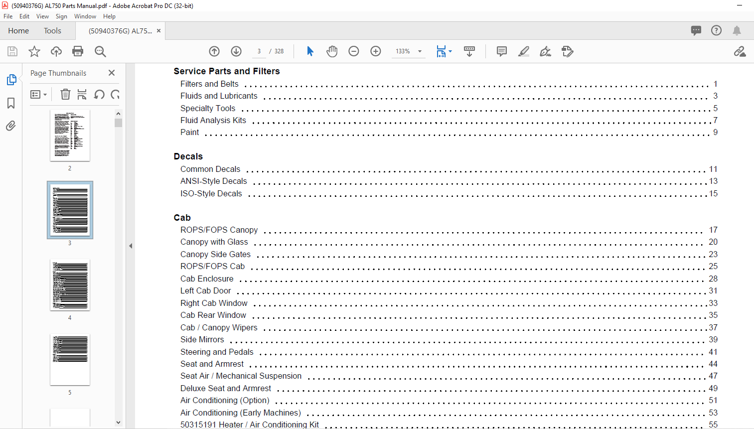
TABLE OF CONTENTS:
Gehl 750 AL750 Articulated Loader Parts Manual 50940376 – PDF DOWNLOAD
Service Parts and Filters
Filters and Belts 1
Fluids and Lubricants 3
Specialty Tools 5
Fluid Analysis Kits 7
Paint 9
Decals
Common Decals 11
ANSI-Style Decals 13
ISO-Style Decals 15
Cab
ROPS/FOPS Canopy 17
Canopy with Glass 20
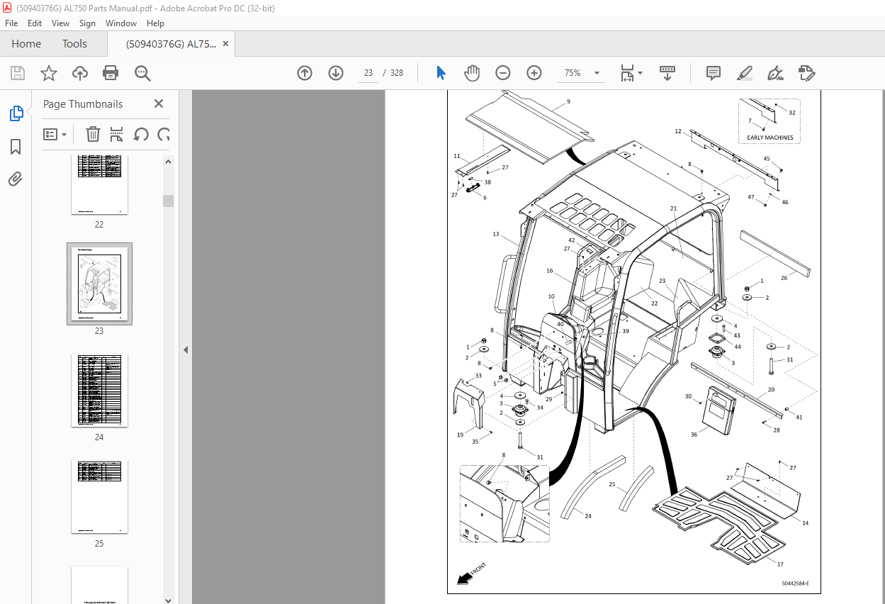
Canopy Side Gates 23
ROPS/FOPS Cab 25
Cab Enclosure 28
Left Cab Door 31
Right Cab Window 33
Cab Rear Window 35
Cab / Canopy Wipers 37
Side Mirrors 39
Steering and Pedals 41
Seat and Armrest 44
Seat Air / Mechanical Suspension 47
Deluxe Seat and Armrest 49
Air Conditioning (Option) 51
Air Conditioning (Early Machines) 53
50315191 Heater / Air Conditioning Kit 55
Air Conditioning / Engine 57
Firewall Plug-No HVAC 60
Cab Heater (Later Machines) 63
Heater Assembly 65
Cab Heater (Early Machines) 67
50318537 / 50318536 Heater Assembly 69
Cab Heater Hoses 71
Chassis
Rear Chassis – SN 00070176 and After 73
Rear Chassis – SN 00070175 and Before 75
Front Chassis 77
Lower Step Kit (Option) 80
Counterweight 83
Fenders 85
Toolbox (Option) 87
Hitch 89
Tie Down Shackle (Option) 91
Lift Structure
Lift Structure 93
Powered Attach 95
50314667 Powered Attach Cylinder 97
201463 Powered Attach Cylinder 99
4-Point Powered Attach 101
Euro-Style Powered Attach 103
176670 Powered Attach Cylinder 105
Buckets 107
Engine / Power
Engine Left Side 109
Engine Right Side 112
Air Cleaner 115
186014 Air Cleaner Assembly 117
Engine Block Heater 119
Radiator / Cooler 121
50307934 Engine Fan Gear Motor 124
Engine Cover – SN 00060199 and After 127
Engine Cover – SN 00060198 and Before 129
Engine / Sound Suppression 131
Hydraulics
Lift Structure Hydraulics 133
50307148 Tilt Cylinder 135
50306877 Lift Cylinder 137
50307333 Lift Cylinder 139
50310176 Lower Cylinder Valve 141
No Hydraglide 143
Hydraglide (Option) 145
50310232 Hydraglide Valve 147
Auxiliary Hydraulics / Standard (Control Valve Forward) 149
50310175 Auxiliary Hydraulics / Drain Valve 151
Auxiliary Hydraulics / Standard (Control Valve Back) 153
50307761 Gear Pump – 32CC / 14CC 155
Auxiliary Hydraulics / 2nd (Control Valve Forward) 157
Auxiliary Hydraulics / 2nd (Control Valve Back) 159
Auxiliary Drain Diverter Valve 161
Auxiliary Hydraulics / High-Flow Connectors 163
Auxiliary Hydraulics / High-Flow 165
50307763 Gear Pump – 32CC/21CC/14CC 168
50308395 High-Flow Valve 171
Chassis Hydraulics (1 of 2) – SN 00070064 and After 173
Chassis Hydraulics (2 of 2) – SN 00070164 and After 176
Chassis Hydraulics (1 of 2) – SN 00070063 and Before 180
Chassis Hydraulics (2 of 2) – SN 00070163 and Before 184
50309807 Joystick 188
50307404 Pilot Control Valve 191
50306866 Steering Cylinder 193
50313416 Steering Valve 195
50315496 Multi-Function Manifold – SN 00070164 and After 197
50310855 Multi-Function Manifold – SN 00070163 and Before 199
Drive Circuit (Later Machines) 201
Drive Circuit (Early Machines) 204
50307020 Hydraulic Filter 208
50307092 Bent Axis Motor (1 of 3) 211
50307092 Bent Axis Motor (2 of 3) 213
50307092 Bent Axis Motor (3 of 3) 215
50308001 Axial Piston Pump (1 of 3) 217
50308001 Axial Piston Pump (2 of 3) 219
50308001 Axial Piston Pump (3 of 3) 221
Electrical
Front Chassis Electrical (1 of 2) 223
Front Chassis Electrical (2 of 2) 225
Rear Chassis Electrical – SN 00070228 and After 227
Rear Chassis Electrical – SN 00070227 and Before 229
Chassis Harness Fuses, Relays and Diodes 231
Engine Electrical (Stage V) 233
Engine Electrical (Tier 4) 235
Cab/Canopy Electrical 237
Console Switches 239
Easy Manager / No Keypad 241
Radio Kit (Option) 243
2-Speed Module (High / Low Drive Speed) 245
2-Speed Module – With Constant Speed 247
3-Speed Module 249
3-Speed Module – With Constant Speed 251
14-Pin Connector (Option) 253
Front Electrical Auxiliary (Option) 255
Rear Electrical Auxiliary (Option) 257
Road Lights (Option) 259
Directional / Marker Lights (Option) 261
Rear Licence Plate (Option) 263
Front Licence Plate (Option) 265
Standard Work Lights (Option) 267
LED Work Lights (Option) 269
Rear Lights Connection (Option) 271
Rotating Beacon (Option) 273
Strobe Beacon (Option) 275
Back Up Alarm (Option) 277
Drivetrain
Axle Assembly 279
Front Axle Components 281
Front Disc Brake Components 287
Rear Axle Components 289
Rear Axle Motor Mount 295
50307320 Driveshaft 297
Wheels and Tires 299
Appendix A:Pages Index 301
Appendix B:Parts Index 303
DESCRIPTION:
Gehl 750 AL750 Articulated Loader Parts Manual 50940376 – PDF DOWNLOAD
INTRODUCTION:
- For your safety and continued proper operation, use only genuine XPRT® Genuine Parts. When ordering service parts, specify the correct part number, full description, quantity required, the unit model number, and serial number. The model and serial number decal for this unit are located on the left chassis upright.
- Manitou Americas reserves the right to make changes or improvements in the design or construction of any part of the unit without incurring the obligation to install such changes on any previously delivered units. Purchase equivalent, quality XPRT tires for your loader. Contact your dealer for replacement tire information. Replacement batteries are not provided by Manitou Americas. Battery specifications are listed in the Electrical section where the battery is shown. ALL REPLACEMENT BATTERIES MUST BE PURCHASED LOCALLY.
How to Use This Manual:
- “Right” and “Left” are determined from a position sitting on the seat and facing forward. Unless otherwise indicated, all parts page graphics are shown as viewed from the front left. If the view is from a different perspective, a directional arrow on the lower-left corner will identify the front of the machine. Items shown in the parts list that do not have part numbers are shown for reference purposes only and are NOT available for purchase. Dimensions are in inches unless otherwise specified.
- Refer to the abbreviations table to the right for various fastener descriptions. Standard hardware torque values are provided at the end of this manual. For parts requiring non-standard torque values, the correct torque value will appear on the parts page graphic or parts list next to the corresponding item number.
IMAGES PREVIEW OF THE MANUAL:
More products