$31
Gehl 753Z Compact Excavator Service Manual 918164 – PDF DOWNLOAD
Gehl 753Z Compact Excavator Service Manual 918164 – PDF DOWNLOAD
FILE DETAILS:
Gehl 753Z Compact Excavator Service Manual 918164 – PDF DOWNLOAD
Language : English
Pages : 184
Downloadable : Yes
File Type : PDF
Size: 21.7 MB
IMAGES PREVIEW OF THE MANUAL:
DESCRIPTION:
Gehl 753Z Compact Excavator Service Manual 918164 – PDF DOWNLOAD
Operation:
- This service manual contains important information about safely servicing the machine,
correctly and economically. It serves as a reference for experienced users, helps to avoid
hazardous situations, and reduces repair costs and downtimes. Additionally, the reliability
and the service life of the machine will be increased by following the instructions in this
manual. - Proper and careful work is the best protection against accidents!
Operational safety and readiness of the machine depends not only upon operator skill, but
also upon proper maintenance and service. - Always use Gehl original service parts when performing maintenance and repair work.
This ensures operational safety and readiness of the machine, and maintains its value.
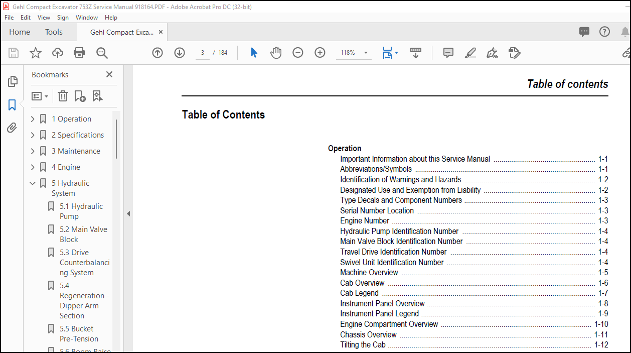
TABLE OF CONTENTS:
Gehl 753Z Compact Excavator Service Manual 918164 – PDF DOWNLOAD
1 Operation………………………………………………………………. 7
1.1 Important Information about this Service Manual……………………….. 7
1.2 Abbreviations/Symbols………………………………………………. 7
1.3 Identification of Warnings and Hazards……………………………….. 8
1.4 Designated Use and Exemption from Liability…………………………… 8
1.5 Type Decals and Component Numbers……………………………………. 9
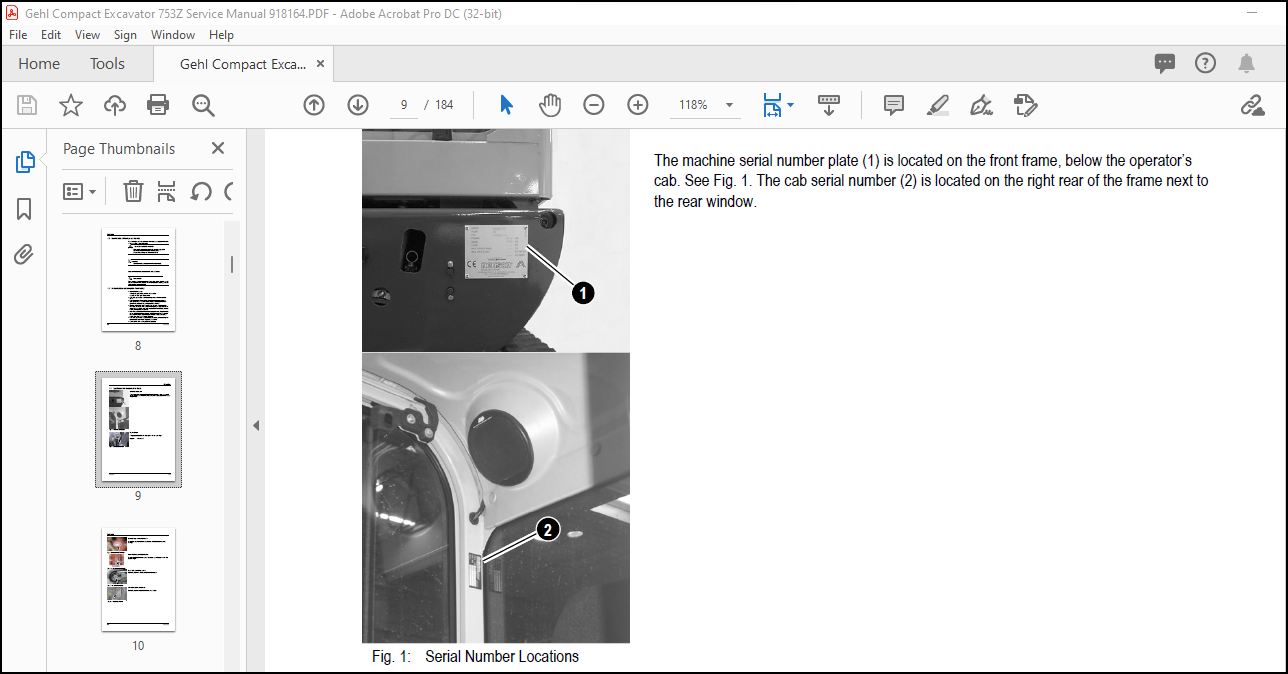
Serial Number Location…………………………………………………. 9
Engine Number…………………………………………………………. 9
Hydraulic Pump Identification Number…………………………………….. 10
Main Valve Block Identification Number…………………………………… 10
Travel Drive Identification Number………………………………………. 10
Swivel Unit Identification Number……………………………………….. 10
1.6 Machine Overview…………………………………………………… 11
1.7 Cab Overview………………………………………………………. 12
1.8 Cab Legend………………………………………………………… 13
1.9 Instrument Panel Overview…………………………………………… 14
1.10 Instrument Panel Legend……………………………………………. 15
1.11 Engine Compartment Overview………………………………………… 16
1.12 Chassis Overview………………………………………………….. 17
1.13 Tilting the Cab…………………………………………………… 18
Tilting the Cab Down…………………………………………………… 19
1.14 SAE Operating Controls (Standard)…………………………………… 20
1.15 ISO Operating Controls (Selectable)…………………………………. 21
1.16 Boom Slew/Auxiliary Hydraulics Pedal………………………………… 22
1.17 Dozer Blade………………………………………………………. 22
1.18 Throttle Lever……………………………………………………. 23
1.19 Operator’s Seat Adjustments………………………………………… 24
1.20 Ventilation………………………………………………………. 26
Windshield……………………………………………………………. 26
1.21 Cab Door Latch Release…………………………………………….. 27
1.22 Interior Light……………………………………………………. 27
1.23 Tool Kit and Cab Jack Handle……………………………………….. 27
1.24 Cab Heat Control………………………………………………….. 28
1.25 Recirculated Air Mode……………………………………………… 28
1.26 Hydraulics/Swiveling and Boom Rotation Pedal Adjustment……………….. 29
2 Specifications………………………………………………………….. 31
2.1 Chassis…………………………………………………………… 31
2.2 Engine……………………………………………………………. 31
2.3 Hydraulic System…………………………………………………… 33
2.4 Undercarriage and Swivel Unit……………………………………….. 34
2.5 Dozer Blade……………………………………………………….. 34
2.6 Electrical System………………………………………………….. 35
2.7 Sound Levels………………………………………………………. 37
2.8 Coolant Compound Table……………………………………………… 37
2.9 Model-Specific Tightening Torques……………………………………. 37
2.10 General Specifications…………………………………………….. 38
2.11 Extended Dipper Arm Lift Capacities…………………………………. 40
2.12 Lift Capacities with Counterweight………………………………….. 41
2.13 Lift Capacities with Extended Dipper Arm and Counterweight…………….. 42
2.14 Bucket Geometry…………………………………………………… 43
3 Maintenance…………………………………………………………….. 45
3.1 General Information Care and Servicing……………………………….. 45
Care and Servicing…………………………………………………….. 45
Maintenance Safety…………………………………………………….. 46
3.2 Fluids and Lubricants………………………………………………. 47
3.3 Maintenance Decal Symbols…………………………………………… 49
3.4 Maintenance Decal………………………………………………….. 50
3.5 Maintenance Schedule……………………………………………….. 51
3.6 General Maintenance………………………………………………… 54
3.7 Lubrication……………………………………………………….. 56
3.8 Fuel System……………………………………………………….. 57
Fuel Filter…………………………………………………………… 58
Fuel Shut-Off Valve, Fuel Prefilter and Water Separator……………………. 58
Purging Air from the Fuel System………………………………………… 59
3.9 Engine Lubrication System…………………………………………… 60
3.10 Changing Engine Oil and Filter……………………………………… 60
3.11 Coolant System……………………………………………………. 62
Checking Coolant Level…………………………………………………. 62
3.12 Air Cleaner Service……………………………………………….. 63
Dust Valve Functional Check…………………………………………….. 64
3.13 Checking and Adjusting V-Belt Tension……………………………….. 65
Checking and Adjusting Air Conditioning V-Belt Tension…………………….. 66
3.14 Pressure Check……………………………………………………. 67
3.15 Test Report………………………………………………………. 73
3.16 Hydraulic System………………………………………………….. 76
Checking Hydraulic Oil Level……………………………………………. 76
Changing Hyraulic Oil………………………………………………….. 78
Hydraulic Cooling System……………………………………………….. 78
Adding Hydraulic Oil…………………………………………………… 79
Specific Safety Instructions……………………………………………. 80
3.17 Track System……………………………………………………… 81
Changing Final Drive Oil……………………………………………….. 81
3.18 Electrical System…………………………………………………. 84
Using a Booster Battery (Jump-Starting)………………………………….. 85
3.19 Cab Heater Filter…………………………………………………. 87
4 Engine…………………………………………………………………. 89
4.1 Engine Overview……………………………………………………. 89
4.2 Fuel System……………………………………………………….. 91
4.3 Removing the Cylinder Head Cover…………………………………….. 92
4.4 Checking and Adjusting Valve Tip Clearance……………………………. 92
4.5 Cylinder Head Bolt Tightening Order………………………………….. 94
4.6 Checking the Injection Nozzles………………………………………. 94
4.7 Checking the Nozzle Jet…………………………………………….. 95
4.8 Injection Timing…………………………………………………… 96
4.9 Adjusting Engine RPM……………………………………………….. 97
4.10 Checking Compression………………………………………………. 97
4.11 Checking the Coolant Thermostat…………………………………….. 98
4.12 Checking the Thermal Switch………………………………………… 98
4.13 Oil Pressure Switch……………………………………………….. 99
4.14 Checking the Coolant Circuit……………………………………….. 99
4.15 Engine Troubleshooting……………………………………………..100
5 Hydraulic System…………………………………………………………103
5.1 Hydraulic Pump……………………………………………………..103
5.2 Main Valve Block……………………………………………………108
5.3 Drive Counterbalancing System………………………………………..113
5.4 Regeneration – Dipper Arm Section…………………………………….115
5.5 Bucket Pre-Tension………………………………………………….115
5.6 Boom Raise…………………………………………………………116
5.7 Check Valve (Load Retaining Valve)……………………………………117
Raising the Boom……………………………………………………….117
Lowering the Boom………………………………………………………117
5.8 Dipper Arm Cylinder, Extend………………………………………….118
5.9 Secondary Pressure Limiting Valves for the Auxiliary Hydraulics (Option)….119
5.10 Pilot Valves………………………………………………………120
5.11 Valves……………………………………………………………125
5.12 Travel Drive………………………………………………………130
5.13 Travel Drive………………………………………………………132
5.14 Swivel Unit……………………………………………………….136
5.15 Swivel Joint………………………………………………………141
5.16 Breather Filter……………………………………………………142
5.17 Troubleshooting the Hydraulic System…………………………………143
5.18 Main Valve Block Diagram……………………………………………145
5.19 Hydraulic Diagram)…………………………………………………146
5.20 Hydraulic Diagram………………………………………………….147
5.21 Main Valve Block Diagram with 3rd Control Circuit……………………..148
6 Electrical System………………………………………………………..149
6.1 Ohm’s Law (Current, Voltage, Resistance); Power………………………..149
6.2 Measuring Equipment, Measuring Methods………………………………..149
6.3 Cable Color Coding………………………………………………….150
6.4 Relays…………………………………………………………….151
6.5 Electric Units……………………………………………………..151
6.6 Fuse Box in Instrument Panel…………………………………………151
6.7 Main Fuse Box with Relays……………………………………………152
6.8 Relays…………………………………………………………….152
6.9 Lubrication Block Accessory Power Socket………………………………153
6.10 Joystick Tip Switches………………………………………………153
6.11 Instrument Panel Overview…………………………………………..154
6.12 Switch Overview……………………………………………………155
6.13 Alternator………………………………………………………..156
6.14 Starter…………………………………………………………..156
6.15 Boom Working Light Wiring Harness……………………………………157
6.16 Wiring Diagram Legend………………………………………………158
6.17 Wiring Diagram…………………………………………………….159
6.18 Engine – Chassis Wiring Harness……………………………………..160
6.19 Engine – Chassis Wiring Harness……………………………………..161
6.20 Wiring Harness: Switches……………………………………………162
6.21 Wiring Harness: Switches……………………………………………163
6.22 Cab Roof Wiring Harness…………………………………………….164
6.23 Armrest Wiring Harness……………………………………………..165
7 Options…………………………………………………………………167
7.1 Air Conditioning……………………………………………………167
7.2 Counterweight………………………………………………………175
7.3 Extended Dipper Arm…………………………………………………175
7.4 Control Circuit Hydraulic Coupling Connections…………………………176
7.5 3rd Control Circuit Connections………………………………………176
7.6 Auxiliary Hydraulics Connections……………………………………..177
7.7 Automatic Idling Speed………………………………………………178
More products