$34
Gehl 80 Series Variable Chamber Round Balers 2480 2580 2680 2780 2880 Parts Manual 909796 – PDF
Gehl 80 Series Variable Chamber Round Balers 2480 2580 2680 2780 2880 Parts Manual 909796 – PDF DOWNLOAD
FILE DETAILS:
Gehl 80 Series Variable Chamber Round Balers 2480 2580 2680 2780 2880 Parts Manual 909796 – PDF DOWNLOAD
Language : English
Pages : 204
Downloadable : Yes
File Type : PDF
Size: 7.58 MB
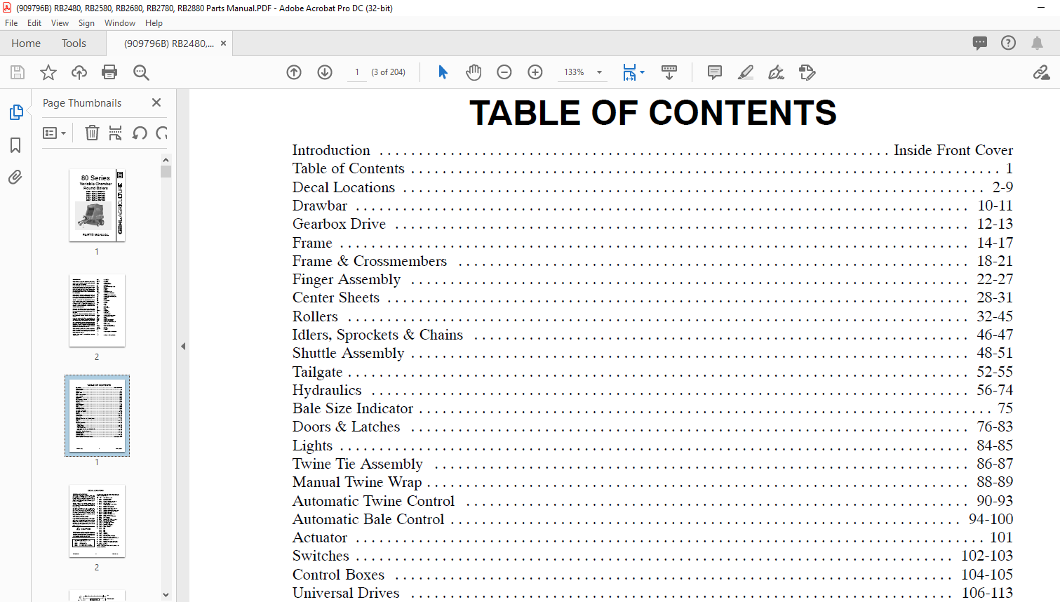
TABLE OF CONTENTS:
Gehl 80 Series Variable Chamber Round Balers 2480 2580 2680 2780 2880 Parts Manual 909796 – PDF DOWNLOAD
Introduction Inside Front Cover
Table of Contents 1
Decal Locations 2-9
Drawbar 10-11
Gearbox Drive 12-13
Frame 14-17
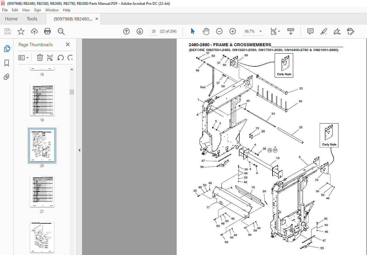
Frame & Crossmembers 18-21
Finger Assembly 22-27
Center Sheets 28-31
Rollers 32-45
Idlers, Sprockets & Chains 46-47
Shuttle Assembly 48-51
Tailgate 52-55
Hydraulics 56-74
Bale Size Indicator 75
Doors & Latches 76-83
Lights 84-85
Twine Tie Assembly 86-87
Manual Twine Wrap 88-89
Automatic Twine Control 90-93
Automatic Bale Control 94-100
Actuator 101
Switches 102-103
Control Boxes 104-105
Universal Drives 106-113
Transmissions 114-115
Spindle & Wheel Assembly & TDC Cylinder 116
Hitchjacks 117
Pickup 118-157
Windguard 158
Options & Accessories 159-169
Lacing Kits 159
Steering Monitor 160-163
Crowder Wheels 164-165
Pickup Gauge Wheels 166
Safety Chain, Bale Ramps & 1000 RPM Kit 167
Chain Oiler 168-169
Service Kits – Electrical Connectors 170-173
Electrical Diagrams 174-178
Alphabetical Index 179
Numerical Index 180-199
Hydraulic Fitting Data 200
Standard Hardware Torque specifications Inside Back Cover
DESCRIPTION:
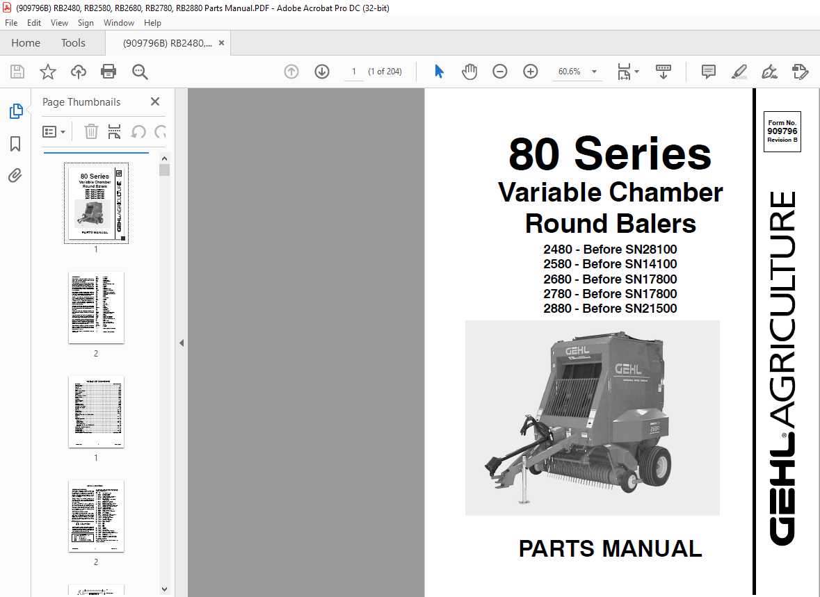
Gehl 80 Series Variable Chamber Round Balers 2480 2580 2680 2780 2880 Parts Manual 909796 – PDF DOWNLOAD
2480 – Before SN28100
2580 – Before SN14100
2680 – Before SN17800
2780 – Before SN17800
2880 – Before SN21500
Introduction :
When ordering service parts, specify the correct part number, full description, quantity required, the unit model number and serial number. The model number and serial number for the Baler are on a decal located under the top channel, near the center column of the right frame assembly.
- “Right’’ and “left’’ are determined from a position standing at the rear of the unit facing the direction of travel. From this position, the Baler drive sprocket on the transmission output shaft is on the left side. GEHL Company reserves the right to make changes or improvements in the design or construction of any part of the unit without incurring the obligation to install such changes on any previously delivered units.
- Refer to the abbreviations table located on this page for the various fastener descriptions. Standard attaching hardware torque values are also provided on the inside back cover. In the exploded view parts list, Reference Numbers may have additional information following the Reference Number.
- A tear drop symbol will indicate an application of a “wet” product such as oil, and the number inside the tear drop will correspond to the description in the parts list. Also, a number inside a hexagon will be the torque value required, in foot pounds, on the associated Reference Number.
- Items shown in the parts list that do not have Reference Numbers are shown for reference purposes only and are NOT available for purchase. Unless otherwise specified, all cap screws or bolts are Grade 5, cadmium plated; hexagon nuts for Grade 5 screws or bolts are Grade B; hexagon nuts for other screws or bolts are Grade A.
IMAGES PREVIEW OF THE MANUAL:
More products