$33
Gehl 802 Compact Excavator Service Manual 918158 – PDF DOWNLOAD
Gehl 802 Compact Excavator Service Manual 918158 – PDF DOWNLOAD
FILE DETAILS:
Gehl 802 Compact Excavator Service Manual 918158 – PDF DOWNLOAD
Language : English
Pages : 156
Downloadable : Yes
File Type : PDF
Size: 17.2 MB
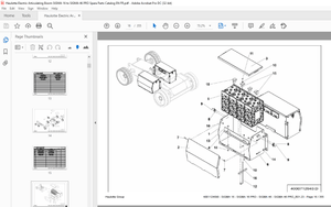
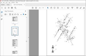
IMAGES PREVIEW OF THE MANUAL:
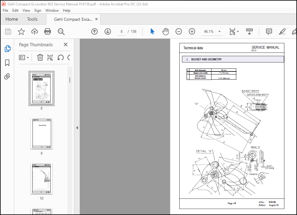
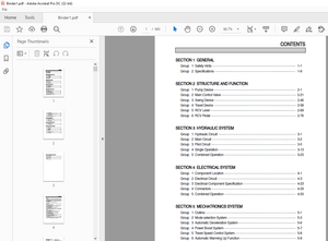
TABLE OF CONTENTS:
Gehl 802 Compact Excavator Service Manual 918158 – PDF DOWNLOAD
A Technical data
Dimensions …………………………………………………………………………………………………….. A2
Bucket and Geometry……………………………………………… ………………………………….. A4
Lift Capacity Chart …………………………………………………………………………………………….. A6
Hydraulic System …………………………………………………………………………………………….. A8
Diesel Engine Specifications …………………………………………………………………………….. A10
B Maintenance
Maintenance Chart ……………………………………………………………………………………………. B2
Maintenance General ……………………………………………………………………………………….. B5
Lubricants ……………………………………………………………………………………………………….. B6
Lubrication Chart (points)…………………………………………………………………………………… B8
Hydraulic System …………………………………………………………………………………………….. B9
Hydraulic Pump ……………………………………………………………………………………………….. B18
Hose Burst Protection Valve……………………………………………………………………………… B19
Drive Unit ………………………………………………………………………………………………………… B19
Swivel Unit ………………………………………………………………………………………………………. B20
Diesel Engine …………………………………………………………………………………………………. B21
Undercarriage …………………………………………………………………………………………………. B31
Hydraulic Oil Tank ……………………………………………………………………………………………. B32
Fuel Tank………………………………………………………………………………………………………… B34
C Hydraulic
Hydraulic System / Diagrams. …………………………………………………………………………… C2
Position of Components …………………………………………………………………………………… C5
Hydraulic Pump ……………………………………………………………………………………………….. C8
Pilot Oil Supply Unit …………………………………………………………………………………………. C16
Main Valve Block …………………………………………………………………………………………….. C22
Second Valve Block ………………………………………………………………………………………… C48
Pilot Control Valves …………………………………………………………………………………………. C51
Swivel Unit ………………………………………………………………………………………………………. C57
Shuttle Valves (swivel motor brake)…………………………………. ……………………………. C64
Drive Unit ………………………………………………………………………………………………………… C65
Swivel Joint …………………………………………………………………………………………………….. C68
Switch Valve ……………………………………………………………………………………………………. C69
Load Lowering Valve ……………………………………………………………………………………….. C70
Hydraulic Oil Tank ……………………………………………………………………………………………. C71
D Diesel Engine
Diesel Engine Specifications …………………………………………………………………………….. D2
E Electrical
Electrical Wiring Diagram (up to serial number AB00473) ……………………………………… E2
Relay Position …………………………………………………………………………………………………. E6
Solenoid Stop …………………………………………………………………………………………………. E7
Glow Control Lamp Relay Plug ………………………………………………………………………….. E8
Fuse Box………………………………………………………………………………………………………… E9
Electrical Wiring Diagram (from serial number AB00473) ………………………………………. E12
Armrest Connections………………………………………………………………………………………… E14
TABLE OF CONTENTS (Continued)
Chapter Page
F Operating Elements
Component Designation …………………………………………………………………………………… F2
Joystick Consoles Component Designation……………………………………………… …… F5
Joystick Functions …………………………………………………………………………………………… F7
Auxiliary Hydraulics / Arm Swing ……………………………………………………………………….. F9
Lifting the Excavator …………………………………………………………………………………………. F10
More products