$23
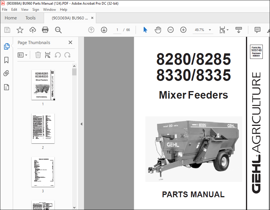
Gehl 8280 8285 8330 8335 Mixer Feeders Parts Manual(909748) – PDF DOWNLOAD
Gehl 8280 8285 8330 8335 Mixer Feeders Parts Manual(909748) – PDF DOWNLOAD
FILE DETAILS:
Gehl 8280 8285 8330 8335 Mixer Feeders Parts Manual(909748) – PDF DOWNLOAD
Language : English
Pages : 66
Downloadable : Yes
File Type : PDF
Size: 2.14 MB
TABLE OF CONTENTS:
Gehl 8280 8285 8330 8335 Mixer Feeders Parts Manual(909748) – PDF DOWNLOAD
Introduction Inside Front Cover
Table of Contents 1
Decal Locations 2-7
Hitch, Axle & Weighbars 8-11
Main Drive 12-13
Augers & Auger Bearings 14-15
Auger Drives 16-17
Chaincase 18-21
Chaincase Mounting & Cover 22
Auger Drive Cover 23
Discharge Door & Hydraulics 24-25
One-Piece Discharge Conveyor 26-29
Two-Piece Discharge Conveyor 30-33
Transport Lights 34-35
Component Breakdowns 36-45
Augers 36-37
540 RPM PTO (Standard) 38-39
1000 RPM PTO (Optional) 40
Hydraulic Cylinders (Discharge Door & 2-Piece Discharge Conveyor) 41
Gearbox (Model 9) 42
Gearbox (Model 8) 43
Hitchjack 44-45
Accessories 46-50
Single Valve Conversion Kit 46
Knife Kit 47
Paddle Kits 47
Safety Tow Chain 48
Ladder Kits 48
Battery Box 49
Magnet Assembly 49
3-Point Scale Stand 49
Remote Scale Indicator (Requires Model 3200 Scale) 50
Audible & Visual Scale Alarms (Models 2100 & 3200 Only) 50
1000 RPM Conversion Kit 51
Scale Alarm Kit 51
Short Conveyor Magnet 52-53
Tank Liner Kits 54-55
Alphabetical Index 56
Numerical Index 57-62
Standard Hardware Torque specifications Inside B
DESCRIPTION:
Gehl 8280 8285 8330 8335 Mixer Feeders Parts Manual(909748) – PDF DOWNLOAD
Introduction
- When ordering service parts, specify the correct part number, full description, quantity required, the unit model number and serial number. The Mixer Feeder model and serial number is on a plate located on the left side of the Main Frame.
- “Right” and “Left” are determined from a position standing behind the Mixer Feeder facing the direction of travel. From this position, the Discharge Gate is on the “left” side. GEHL Company reserves the right to make changes or improvements in the design or construction of any part of the unit without incurring the obligation to install such changes on any previously delivered units.
- Refer to the abbreviations table located on this page for the various fastener descriptions. Standard attaching hardware torque values are also provided on the inside back cover. In the exploded view parts list, Reference Numbers may have additional information following the Reference Number.
- A Tear Drop symbol will indicate an application of a “wet” product such as oil, and the number inside the Tear Drop will correspond to the description in the Parts List. Also, a number inside of a hexagon will be the torque value required, in foot pounds, on the associated Reference Number.
- Items shown in the parts list that do not have Reference Numbers are shown for reference purposes only and are NOT available for purchase. Unless otherwise specified, all Cap Screws or Bolts are Grade 5, cadmium or zinc plated; Hexagon Nuts for Grade 5 Screws or Bolts are Grade B; Hexagon Nuts for other Screws or Bolts are Grade A.
IMAGES PREVIEW OF THE MANUAL:
More products