$23
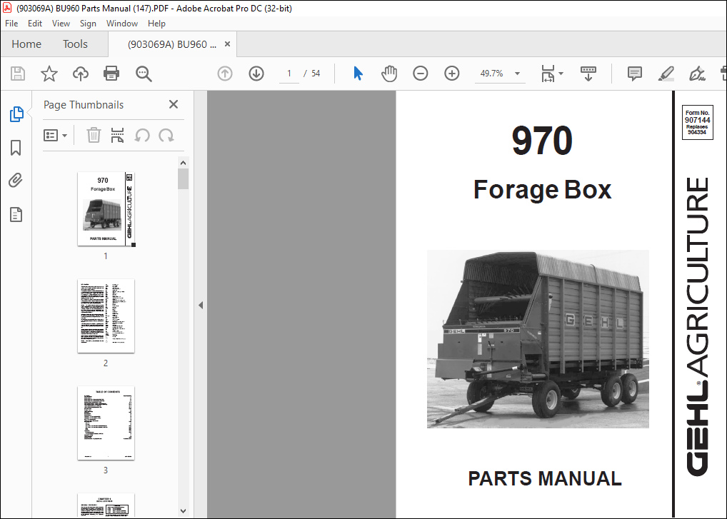
Gehl 970 Forage Box Parts Manual(907144) – PDF DOWNLOAD
Gehl 970 Forage Box Parts Manual(907144) – PDF DOWNLOAD
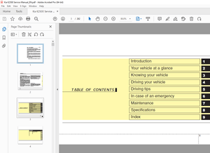
TABLE OF CONTENTS:
Gehl 970 Forage Box Parts Manual(907144) – PDF DOWNLOAD
Inside Front Cover
Table of Contents 1
Decal Locations 2-3
Unloading Unit & 1st Beater (After SN35900) 4-5
Unloading Unit & 1st Beater (Before SN35901) 6-7
Implement Drive, Safety Clutch & Cable 8-11
Powered Clutch Control & Linkage (After SN39700) 12-13
Powered Clutch Control & Linkage (Before SN39701) 14-15
Apron & Beater Drive (After SN39700) 16-17
Apron & Beater Drive (Before SN39701) 18-19
Cross Conveyor 20-21
Platform Feeder 22
Apron Components 23
2nd Beater 24-25
Big 3rd Beater 26
Small 3rd Beater 27
Telescoping PTO Drive (After 43900) 28
Telescoping PTO Drive (Before 43901) 29
Beater Drive Transmission 30
Apron Drive Worm Transmission 31
Box Components 32-41
Side Ties 32
Platforms 33
Side Panels & “Z” Reinforcement (After SN40500) 34-35
Side Panels & “Z” Reinforcement (Before SN39701) 36-37
Ends 38-39
Roofs 40-41
Accessories 42-43
Conveyor Extension 42-43
22T Speed-up Sprocket (Before SN37901) 43
Hydraulic Drive Kit 44
Alphabetical Index 45
Numerical Index 46-49
Standard Hardware Torque Specifications Inside Back Cover
DESCRIPTION:
Gehl 970 Forage Box Parts Manual(907144) – PDF DOWNLOAD
Introduction
- When ordering service parts, specify the correct part number, full description, quantity required, the unit model number and serial number. The model number and serial number for this unit are on a decal located on the right side of the Unloading Unit above the Transmission.
- “Right” and “Left” are determined from a position standing at the rear of the unit and looking toward the direction of travel. From this position, the Cross Conveyor is on the front and discharges from the “left” side. GEHL Company reserves the right to make changes or improvements in the design or construction of any part of the unit without incurring the obligation to install such changes on any previously delivered units.
- Refer to the abbreviations table located on this page for the various fastener descriptions. Standard attaching hardware torque values are also provided on the inside back cover. In the exploded view parts list, Reference Numbers may have additional information following the Reference Number.
- A Tear Drop symbol will indicate an application of a “wet” product such as oil, and the number inside the Tear Drop will correspond to the description in the Parts List. Also, a number inside a hexagon will be the torque value required, in foot pounds, on the associated Reference Number.
- Items shown in the parts list that do not have Reference Numbers are shown for reference purposes only and are NOT available for purchase. Unless otherwise specified, all Cap Screws or Bolts are Grade 5, cadmium or zinc plated; Hexagon Nuts for Grade 5 Screws or Bolts are Grade B; Hexagon Nuts for other Screws or Bolts are Grade A.
IMAGES PREVIEW OF THE MANUAL:
More products