$33
Gehl AL 440 AL 540 Articulated Loader Service Manual 918275 – PDF DOWNLOAD
Gehl AL 440 AL 540 Articulated Loader Service Manual 918275 – PDF DOWNLOAD
FILE DETAILS:
Gehl AL 440 AL 540 Articulated Loader Service Manual 918275 – PDF DOWNLOAD
Language : English
Pages : 220
Downloadable : Yes
File Type : PDF
Size: 10.3 MB
IMAGES PREVIEW OF THE MANUAL:

DESCRIPTION:
Gehl AL 440 AL 540 Articulated Loader Service Manual 918275 – PDF DOWNLOAD
Mandatory Safety Shutdown:
Procedure:
BEFORE cleaning, adjusting, lubricating, fueling or servicing the machine, or leaving it unattended:
1. Bring the machine to a complete stop on a level surface. Avoid parking on an incline or hillside, but if this is not possible, park across the slope and block the tires.2. Be sure all working equipment and/or attachments are stopped and the auxiliary valve is in neutral.3. Lower the lift arm and attachment completely.4. Place forward/reverse drive switch (on top of the joystick) into the neutral position.5. Apply the parking brake. 6. Move the throttle to low idle position and shut off the engine.7. Wait for all movement to stop. Turn the ignition key to the “I” or RUN position and move the multipurpose joystick in all directions to verify that the hydraulic system is de-pressurized.8. Turn off the ignition and remove the key.9. Unfasten the seat belt, remove the ignition key and take it with you. Exit the machine using the hand holds. ONLY when these precautions have been taken can you be sure it is safe to proceed. Failure to follow this procedure could result in death or serious injury.
Before Starting:
• Do not modify the Roll-Over Protective Structure (“ROPS”) unless instructed to do so in Gehl Company-approved installation instructions. Modifications, such as welding, drilling or cutting, can weaken the structure and reduce the protection it provides. A damaged ROPS cannot be repaired – it must be replaced.• To ensure safe operation, replace damaged or worn-out parts with genuine Gehl service parts.• Gehl loaders are designed and intended to be used only wi th Gehl a ttachments and approved attachments. To avoid possible personal injury, equipment damage and performance problems, use only attachments that are approved for use on and within the operating capacity of the machine. Contact the Gehl Company for information on attachment approval and compatibility with specific machine models. Gehl cannot be responsible if the machine is used with a non-approved attachment.• Remove all trash and debris from the machine every day, especially in the engine compartment, to minimize the risk of fire.• Always face the machine and use the hand holds and steps when entering and exiting the machine. Do not jump off the machine.• Do not use starting fluid (ether).• Walk around the machine and inspect it before using it. Look for damage, loose or missing parts, leaks, etc.• Warn all nearby personnel before starting the machine.
TABLE OF CONTENTS:
Gehl AL 440 AL 540 Articulated Loader Service Manual 918275 – PDF DOWNLOAD
Introduction…………………………………………………………………………………………………………….1
Chapter 1 — Safety………………………………………………………………………………………………….3
Mandatory Safety Shutdown Procedure ………………………………………………………………………………………… 4
Before Starting…………………………………………………………………………………………………………………………… 4
During Operation………………………………………………………………………………………………………………………… 5
Service Safety Practices ……………………………………………………………………………………………………………… 6
Fire Hazards ……………………………………………………………………………………………………………………………… 8
Crystalline Silica Exposure ………………………………………………………………………………………………………….. 8
Safety Decals…………………………………………………………………………………………………………………………….. 9
Hazard and Hazard Avoidance Symbols ……………………………………………………………………………………….. 9
Chapter 2 — Specifications ……………………………………………………………………………………11
Fluid Capacities/Lubricants………………………………………………………………………………………………………… 11
Dimensions ……………………………………………………………………………………………………………………………… 12
Weights and Capacities …………………………………………………………………………………………………………….. 14
Engine…………………………………………………………………………………………………………………………………….. 15
Hydraulics ……………………………………………………………………………………………………………………………….. 15
Electrical System ……………………………………………………………………………………………………………………… 15
Sound Levels …………………………………………………………………………………………………………………………… 15
Wheels ……………………………………………………………………………………………………………………………………. 16
FOPS ……………………………………………………………………………………………………………………………………… 16
Chapter 3 — Maintenance………………………………………………………………………………………17
Maintenance Introduction…………………………………………………………………………………………………………… 17
Maintenance Schedule ……………………………………………………………………………………………………………… 18
Engine Maintenance …………………………………………………………………………………………………………………. 20
Air Cleaner ………………………………………………………………………………………………………………………………. 22
Engine Cooling System……………………………………………………………………………………………………………… 23
Fuel System…………………………………………………………………………………………………………………………….. 25
Checking and Adjusting V-belt Tension……………………………………………………………………………………….. 27
Air Conditioning Maintenance …………………………………………………………………………………………………….. 28
Hydraulic System Maintenance ………………………………………………………………………………………………….. 29
Planetary Axles ………………………………………………………………………………………………………………………… 30
Brake Fluid Reservoir ……………………………………………………………………………………………………………….. 32
Wheels and Tires ……………………………………………………………………………………………………………………… 33
Lubrication ………………………………………………………………………………………………………………………………. 35
Electrical System ……………………………………………………………………………………………………………………… 37
Storing the Loader ……………………………………………………………………………………………………………………. 44
Maintenance Log ……………………………………………………………………………………………………………………… 45
Chapter 4 — Operation…………………………………………………………………………………………..49
Operation Safety ………………………………………………………………………………………………………………………. 49
Controls and Switches ………………………………………………………………………………………………………………. 50
Instrument Panel and Indicators …………………………………………………………………………………………………. 52
Cab Controls (Cab only) ……………………………………………………………………………………………………………. 54
Warning Indicators ……………………………………………………………………………………………………………………. 56
Operator’s Seat and Ignition Switch…………………………………………………………………………………………….. 57
Table of Contents
PRINTED IN U.S.A. ii 918275/BP0311
Steering Column ………………………………………………………………………………………………………………………..58
Hand Throttle …………………………………………………………………………………………………………………………….59
Lift Arm Down-Stop…………………………………………………………………………………………………………………….59
Lift/Tilt Lock……………………………………………………………………………………………………………………………….60
Chapter 5 — Chassis……………………………………………………………………………………………..61
Tilting the Platform……………………………………………………………………………………………………………………..61
Lowering the Platform…………………………………………………………………………………………………………………62
Repairing or Replacing Platform Switch ………………………………………………………………………………………..64
Hood Removal …………………………………………………………………………………………………………………………..65
Hood Installation ………………………………………………………………………………………………………………………..66
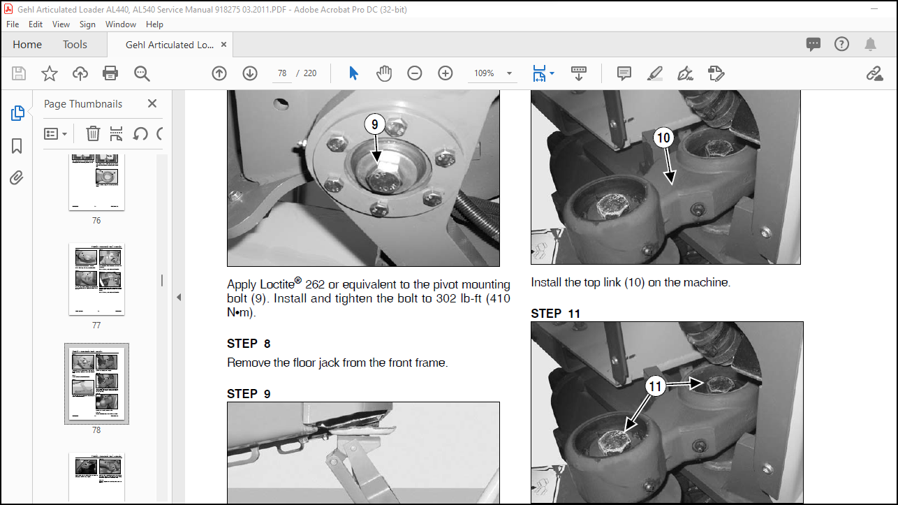
Center/Steering Bearing Removal ………………………………………………………………………………………………..67
Center/Steering Bearing Installation ……………………………………………………………………………………………..70
Lift Arm Removal ……………………………………………………………………………………………………………………….74
Lift Arm Installation …………………………………………………………………………………………………………………….75
Attachment Plate Hydraulics Removal…………………………………………………………………………………………..77
Attachment Plate Hydraulics Installation………………………………………………………………………………………..78
Chapter 6 — Engine……………………………………………………………………………………………….79
Engine Removal…………………………………………………………………………………………………………………………79
Engine Installation………………………………………………………………………………………………………………………83
Drive Coupling Removal ……………………………………………………………………………………………………………..87
Drive Coupling Installation …………………………………………………………………………………………………………..87
Starter Removal …………………………………………………………………………………………………………………………88
Starter Installation………………………………………………………………………………………………………………………88
Chapter 7 — Cooling System …………………………………………………………………………………89
Radiator/Oil Cooler Removal ……………………………………………………………………………………………………….89
Radiator/Oil Cooler Installation …………………………………………………………………………………………………….92
Chapter 8 — Axles…………………………………………………………………………………………………95
Front Axle Removal ……………………………………………………………………………………………………………………95
Front Axle Installation …………………………………………………………………………………………………………………98
Rear Axle Removal …………………………………………………………………………………………………………………..100
Rear Axle Installation………………………………………………………………………………………………………………..102
Chapter 9 — Hydraulics ……………………………………………………………………………………….103
Work Hydraulics Troubleshooting……………………………………………………………………………………………….103
Hydrostatic Drive System…………………………………………………………………………………………………………..106
Hydraulics Troubleshooting Diagnostic Flow Charts ……………………………………………………………………..107
Drive System Pressure Tests …………………………………………………………………………………………………….121
Work System Pressure Tests …………………………………………………………………………………………………….124
Steering Circuit Pressure Test ……………………………………………………………………………………………………125
2-Spool Control Valve Removal………………………………………………………………………………………………….126
3-Spool Control Valve Removal………………………………………………………………………………………………….128
2-Spool Control Valve Installation……………………………………………………………………………………………….131
3-Spool Control Valve Installation……………………………………………………………………………………………….133
Lift/Tilt Lock, Power-A-Tach® System and Auxiliary Hydraulics Valve Locations ………………………………135
Table of Contents
918275/BP0311 iii PRINTED IN U.S.A
Lift Cylinder Removal………………………………………………………………………………………………………………. 136
Lift Cylinder Installation……………………………………………………………………………………………………………. 137
Tilt Cylinder Removal………………………………………………………………………………………………………………. 138
Tilt Cylinder Installation……………………………………………………………………………………………………………. 138
Steering Cylinder Removal ………………………………………………………………………………………………………. 139
Steering Cylinder Installation ……………………………………………………………………………………………………. 139
Hydraulic Cylinder Disassembly/Assembly…………………………………………………………………………………. 141
Gear/Work Hydraulic Pump Removal ………………………………………………………………………………………… 149
Gear/Work Hydraulic Pump Installation ……………………………………………………………………………………… 149
Piston/Drive Hydraulic Pump Removal ………………………………………………………………………………………. 150
Piston/Drive Hydraulic Pump Installation……………………………………………………………………………………. 152
Hydrostatic Motor Removal………………………………………………………………………………………………………. 153
Hydrostatic Motor Installation……………………………………………………………………………………………………. 155
Steering Control Valve Removal……………………………………………………………………………………………….. 156
Steering Control Valve Removal……………………………………………………………………………………………….. 158
Steering Control Valve Installation…………………………………………………………………………………………….. 159
Steering Control Valve Installation…………………………………………………………………………………………….. 160
Raising Machine for Drive System Troubleshooting …………………………………………………………………….. 161
AL 400 Series Hydraulic Schematic – SN 41250 and Up……………………………………………………………… 163
AL 400 Series Hydraulic Schematic – SN 41249 and Before ………………………………………………………… 164
AL 500 Series Hydraulic Schematic – SN 51242 and Up……………………………………………………………… 165
AL 500 Series Hydraulic Schematic – SN 51241 and Before ………………………………………………………… 166
Chapter 10 — Machine/Drive Controllers ………………………………………………………………167
Machine and Drive Controllers………………………………………………………………………………………………….. 167
Machine Controller………………………………………………………………………………………………………………….. 168
Drive Controller (Plus+1 Module)………………………………………………………………………………………………. 172
Service Communication Kit and PLUS+1 GUIDE Service Tool Software………………………………………… 173
Plus+1 Service Tool Navigation/Overview………………………………………………………………………………….. 174
Software Log Monitoring Screen……………………………………………………………………………………………….. 175
Electrical Inputs/Outputs Monitoring Screen……………………………………………………………………………….. 176
Electrical Status Error Reporting Screen ……………………………………………………………………………………. 177
System Definition Error Count/Timestamp Reset Screen……………………………………………………………… 178
Drive Controller Pedal Calibration Parameters ……………………………………………………………………………. 179
Pump Profiling Screen/Drive “Creep” Adjustment………………………………………………………………………… 179
Pedal Calibration Procedure …………………………………………………………………………………………………….. 181
Chapter 11 — Electrical System……………………………………………………………………………183
Battery Removal …………………………………………………………………………………………………………………….. 183
Battery Installation ………………………………………………………………………………………………………………….. 184
AL 400 Series (Serial Numbers 41250 and up) Complete Electrical Schematic ………………………………. 185
AL 400 Series (Serial Numbers 41250 and up) Steering Column Electrical Schematic …………………….. 186
AL 400 Series (Serial Numbers 41250 and up) Chassis Electrical Schematic …………………………………. 187
AL 400 Series (Serial Numbers 41250 and up) Engine Electrical Schematic…………………………………… 188
AL 400 Series (Serial Numbers 41250 and up) FOPS, Power-A-Tach® and Tail Light
Electrical Schematic………………………………………………………………………………………………………………. 189
AL 500 Series (Serial Numbers 51242 and up) Complete Electrical Schematic (Includes Air
Conditioning Option) ……………………………………………………………………………………………………………… 190
Table of Contents
PRINTED IN U.S.A. iv 918275/BP0311
AL 500 Series (Serial Numbers 51242 and up) Steering Column Electrical Schematic (Includes Air
Conditioning Option) ……………………………………………………………………………………………………………….191
AL 500 Series (Serial Numbers 51242 and up) Chassis Electrical Schematic (Includes Air Conditioning
Option) ………………………………………………………………………………………………………………………………….192
AL 500 Series (Serial Numbers 51242 and up) Engine Electrical Schematic (Includes Air Conditioning
Option) ………………………………………………………………………………………………………………………………….193
AL 500 Series (Serial Numbers 51242 and up) FOPS, CAB, Power-A-Tach® and Tail Light Electrical
Schematic (Includes Air Conditioning Option) …………………………………………………………………………….194
AL 400 Series (Serial Numbers 41249 and below), AL 500 Series (Serial Numbers 51241 and below)
Complete Electrical Schematic …………………………………………………………………………………………………195
Chapter 12 — Troubleshooting …………………………………………………………………………….197
Engine…………………………………………………………………………………………………………………………………….197
Indicator Lamps / Seals and Hoses …………………………………………………………………………………………….199
Hydraulic System……………………………………………………………………………………………………………………..200
Hydrostatic Drive System…………………………………………………………………………………………………………..202
More products