$32
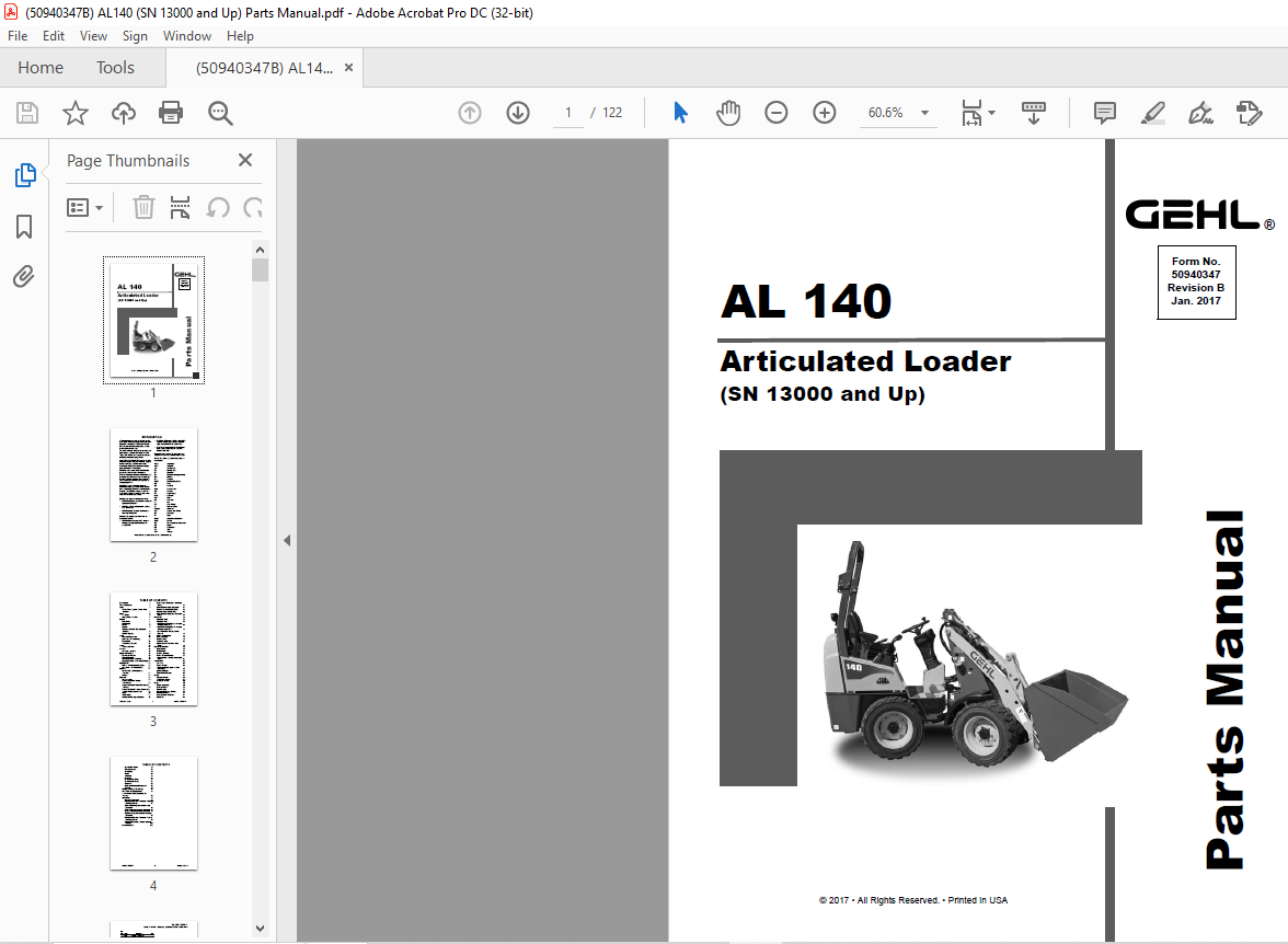
Gehl AL140 Articulated Loader (SN 13000 and Up) Parts Manual 50940347B – PDF DOWNLOAD
Gehl AL140 Articulated Loader (SN 13000 and Up) Parts Manual 50940347B – PDF DOWNLOAD
FILE DETAILS:
Gehl AL140 Articulated Loader (SN 13000 and Up) Parts Manual 50940347B – PDF DOWNLOAD
Language : English
Pages : 122
Downloadable : Yes
File Type : PDF
Size: 6.96 MB
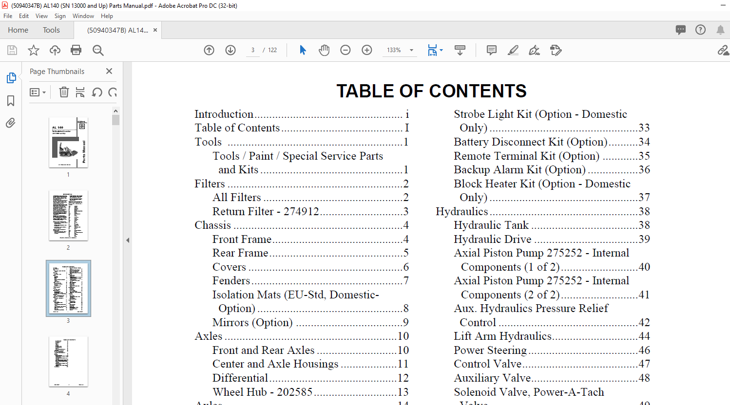
TABLE OF CONTENTS:
Gehl AL140 Articulated Loader (SN 13000 and Up) Parts Manual 50940347B – PDF DOWNLOAD
Introduction………………………………………….. i
Table of Contents………………………………….. I
Tools …………………………………………………..1
Tools / Paint / Special Service Parts
and Kits …………………………………………1
Filters …………………………………………………..2
All Filters ………………………………………..2
Return Filter – 274912……………………….3
Chassis …………………………………………………4
Front Frame……………………………………..4
Rear Frame………………………………………5
Covers …………………………………………….6
Fenders……………………………………………7
Isolation Mats (EU-Std, Domestic-
Option) ………………………………………….8
Mirrors (Option) ………………………………9
Axles ………………………………………………….10
Front and Rear Axles ………………………10
Center and Axle Housings ……………….11
Differential…………………………………….12
Wheel Hub – 202585……………………….13
Axles ………………………………………………….14
Wheels and Tires ……………………………14
Lift Arm ……………………………………………..15
Lift Arm Assembly …………………………15
Operator’s Platform ……………………………..16
Operator’s Platform ………………………..16
Seat and Seatbelt…………………………….18
Steering Column – Standard……………..19
Steering Column – Deluxe (EU Only) .20
ROPS/FOPS………………………………………..22
ROPS – Two-Post and Four-Post ………22
Side Gates – Four-Post ROPS …………23
Controls………………………………………………24
Service Brake, Parking Brake,
Throttle………………………………………..24
Inching ………………………………………….25
Electrical …………………………………………….26
Main Machine ………………………………..26
Battery Cables (w/ Remote
Terminals) ……………………………………27
Battery Cables (w/ Master Disconnect
Switch)………………………………………..28
Battery Cables (w/ Remote Terminals &
Master Disconnect Switch)…………….29
Fuses …………………………………………….30
Work Lights …………………………………..31
Headlights/Tail Lights (Option)………..32
Strobe Light Kit (Option – Domestic
Only) …………………………………………..33
Battery Disconnect Kit (Option)……….34
Remote Terminal Kit (Option) …………35
Backup Alarm Kit (Option) ……………..36
Block Heater Kit (Option – Domestic
Only) …………………………………………..37
Hydraulics…………………………………………..38
Hydraulic Tank ………………………………38
Hydraulic Drive ……………………………..39
Axial Piston Pump 275252 – Internal
Components (1 of 2)……………………..40
Axial Piston Pump 275252 – Internal
Components (2 of 2)……………………..41
Aux. Hydraulics Pressure Relief
Control ………………………………………..42
Lift Arm Hydraulics………………………..44
Power Steering……………………………….46
Control Valve…………………………………47
Auxiliary Valve………………………………48
Solenoid Valve, Power-A-Tach
Valve…………………………………………..49
Hydraulic Cylinders……………………………..50
Lift Cylinder ………………………………….50
Tilt Cylinder…………………………………..51
Steering Cylinder ……………………………52
Power-A-Tach Cylinder…………………..53
4-Point Quick-A-Tach Cylinder (EU
Only) …………………………………………..54
Attachments ………………………………………..55
All-Tach ………………………………………..55
Power-A-Tach………………………………..56
4-Point Hydraulic Quick-A-Tach
(EU Only) ……………………………………57
Buckets (Option)…………………………….58
Pallet Forks (Option) ………………………59
Decals…………………………………………………61
Common Decals……………………………..62
ANSI-Style Decals………………………….64
ISO-Style Decals…………………………….66
Engine ………………………………………………..69
Engine Assembly ……………………………69
Cylinder Block……………………………….70
Gear Housing …………………………………71
Flywheel Housing / Oil Pan……………..72
Exhaust Manifold……………………………73
Cylinder Head and Cover ………………..74
Camshaft ……………………………………….76
50940347/BP0117 II Printed in U.S.A.
TABLE OF CONTENTS
Crankshaft / Piston………………………….77
Cooling System………………………………78
Lubrication…………………………………….79
Starter……………………………………………80
Alternator ………………………………………81
Fuel Line ……………………………………….82
Fuel Injection Valve………………………..83
Fuel Injection Pump………………………..84
Governor ……………………………………….86
Intake and Exhaust Components……….88
Radiator…………………………………………89
Fittings / O-Rings / Seal Rings ………………90
Hose / O-Ring Compatibility…………………91
Abbreviations and Descriptions for
Fittings ……………………………………………..92
Schematics ………………………………………….93
Hydraulic Schematic……………………….93
Complete Electrical Schematic – Standard
Steering Column…………………………..94
Standard Steering Column Electrical
Schematic ……………………………………95
Chassis Harness Electrical Schematic .96
Engine Harness Electrical Schematic ..97
Road Homologation Harness Electrical
Schematic ……………………………………98
Complete Electrical Schematic – Deluxe
Steering Column…………………………..99
Electrical Schematic – Deluxe Steering
Column ……………………………………..100
Numerical Index ………………………………..103
DESCRIPTION:
Gehl AL140 Articulated Loader (SN 13000 and Up) Parts Manual 50940347B – PDF DOWNLOAD
INTRODUCTION:
When ordering service parts, specify the correct part number, full description, quantity required, the unit model number and serial number. For your safety and continued proper operation, use only genuine GEHL service parts. The model and serial number for this unit are on a tag located on a panel on the front of the cabin.
- ”Right” and ”left” are determined from a position sitting on the seat and facing forward. MANITOU AMERICAS, INC. reserves the right to make changes or improvements in the design or construction of any part of the unit without incurring the obligation to install such changes on any previously delivered units.
- Refer to the abbreviations table located on this page for the various fastener descriptions. Standard attaching hardware torque values are also provided on the inside back cover. Metric torque values shown in the illustrations are in Newtonmeters and can be converted to foot-pounds by multiplying by 0.738.
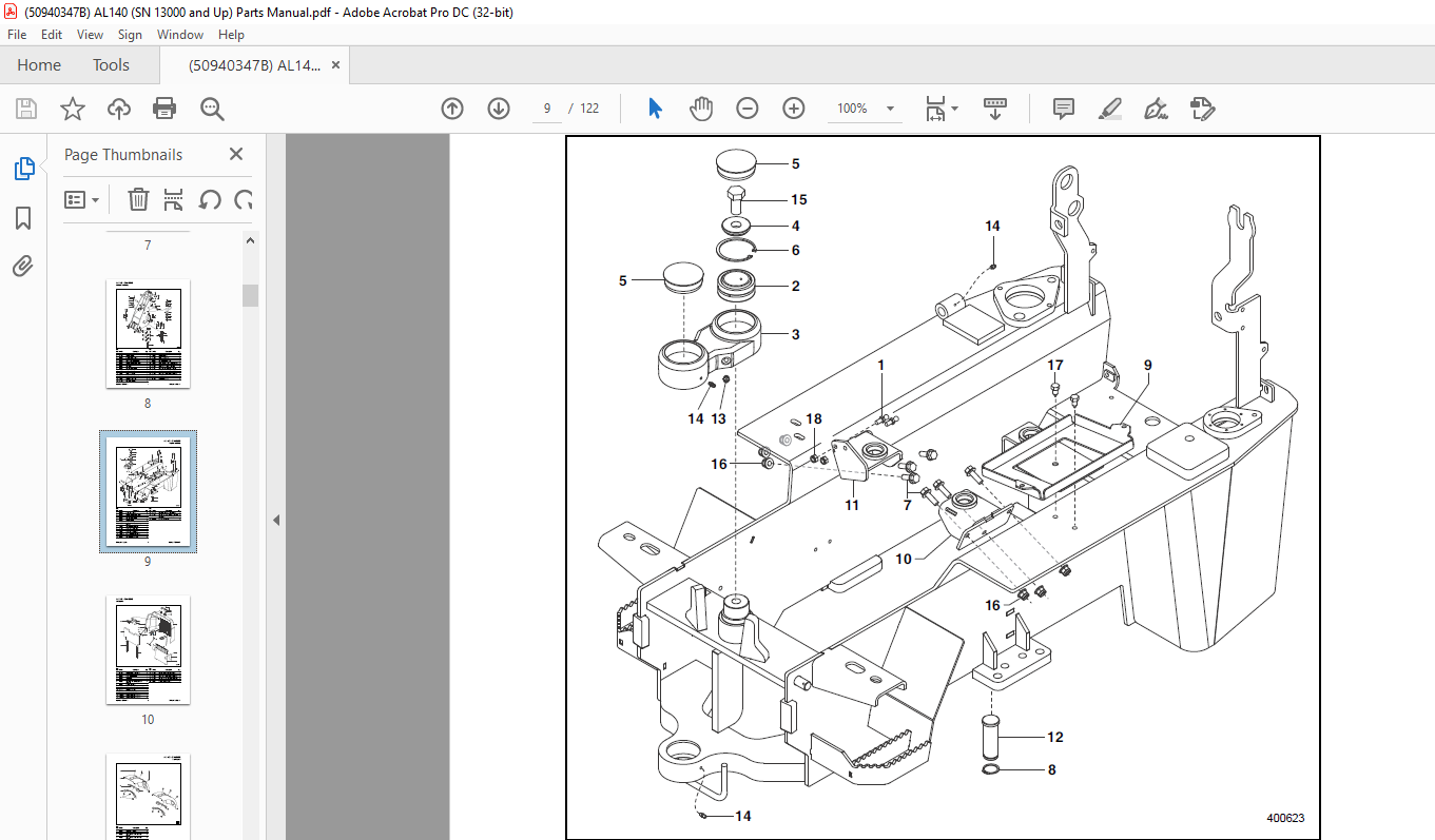
- Specific Reference Numbers, indicating a complete assembly, are circled in some illustrations. A small bag, pictured in some illustrations, indicates a seal kit (seals, o-rings, etc.). In the exploded view parts list, additional information may follow the Reference Number.
Serial number breaks are indicated as follows:
• (SN 999 and before) – indicates serial numbers
up to and including 999.
• (SN 1000 – 2000) – indicates serial numbers
from 1000 to 2000.
• (SN 999 and up) – indicates serial numbers
including 999 and after.
Serial number exceptions and inclusions are
indicated as follows:
• (SN 999 and before except 997) – indicates
serial numbers up to and including 999,
EXCEPT 997.
• (SN 1000 – 2000 except 1996 including 997) –
indicates serial numbers between 1000 and
2000, INCLUDING 997 EXCEPT 1996.
• (SN 2001 and up including 1996) – indicates
serial numbers including 2001 and after,
INCLUDING 1996.
IMAGES PREVIEW OF THE MANUAL:
More products