$33
Gehl AWS36 Wheel Loader Parts Manual 918263 – PDF DOWNLOAD
Gehl AWS36 Wheel Loader Parts Manual 918263 – PDF DOWNLOAD
FILE DETAILS:
Gehl AWS36 Wheel Loader Parts Manual 918263 – PDF DOWNLOAD
Language : English
Pages : 173
Downloadable : Yes
File Type : PDF
Size: 14.1 MB
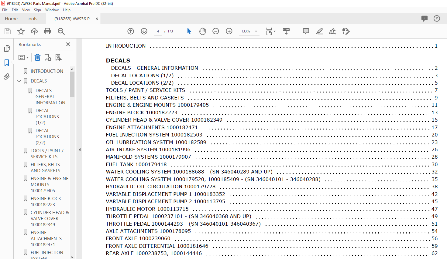
TABLE OF CONTENTS:
Gehl AWS36 Wheel Loader Parts Manual 918263 – PDF DOWNLOAD
INTRODUCTION 1
DECALS
DECALS – GENERAL INFORMATION 2
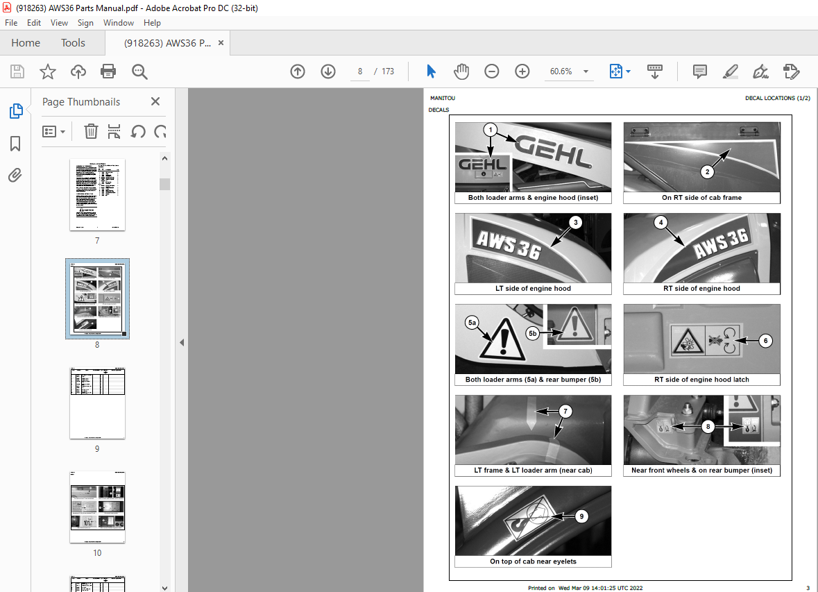
DECAL LOCATIONS (1/2) 3
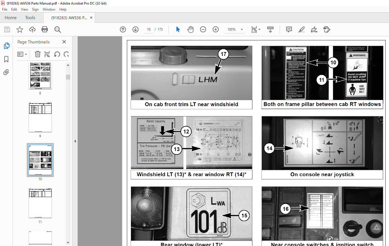
DECAL LOCATIONS (2/2) 5
TOOLS / PAINT / SERVICE KITS 7
FILTERS, BELTS AND GASKETS 9
ENGINE & ENGINE MOUNTS 1000179405 11
ENGINE BLOCK 1000182223 13
CYLINDER HEAD & VALVE COVER 1000182349 15
ENGINE ATTACHMENTS 1000182471 17
FUEL INJECTION SYSTEM 1000182503 20
OIL LUBRICATION SYSTEM 1000182589 23
AIR INTAKE SYSTEM 1000181996 26
MANIFOLD SYSTEMS 1000179907 28
FUEL TANK 1000179418 30
WATER COOLING SYSTEM 1000188688 – (SN 346040289 AND UP) 32
WATER COOLING SYSTEM 1000179520, 1000185409 – (SN 346040101 – 346040288) 35
HYDRAULIC OIL CIRCULATION 1000179728 38
VARIABLE DISPLACEMENT PUMP 1 1000183352 42
VARIABLE DISPLACEMENT PUMP 2 1000113795 45
HYDRAULIC MOTOR 1000113715 47
THROTTLE PEDAL 1000237101 – (SN 346040368 AND UP) 49
THROTTLE PEDAL 1000144293 – (SN 346040101-346040367) 51
AXLE ATTACHMENTS 1000178095 54
FRONT AXLE 1000239060 56
FRONT AXLE DIFFERENTIAL 1000181646 59
REAR AXLE 1000238753, 1000144446 62
REAR AXLE DIFFERENTIAL 1000238725 65
STEERING CYLINDERS (FRONT AND REAR) 1000144445 68
GEAR BOX 1000178099 70
SERVICE BRAKE 1000179598 72
BRAKE PEDAL 1000168148 74
PARKING BRAKE 1000144477 76
HYDRAULIC OIL TANK 1000251353 – (SN 348040549 AND UP) 78
HYDRAULIC OIL TANK 1000180123 – (SN 346040101-346040548) 80
STEERING UNIT 1000144594 82
HYDRAULIC OIL CIRCULATING SYSTEM 1000180106 85
LIFT ARM HYDRAULIC CIRCUIT 1000260207 88
3RD HYDRAULIC CIRCUIT 1000180125 90
HYDRAULIC SYSTEM CONTROL VALVE 1000144904 92
LIFT CYLINDER 1000114865 95
TILT CYLINDER 1000114867 97
OIL PREHEATING SYSTEM 809451 99
BATTERY 1000181381 101
VEHICLE LIGHTING 1000190171 – (SN 346040368 AND UP) 103
VEHICLE LIGHTING 1000181436 – (SN 346040101-3464040367) 106
INSTRUMENT PANEL 1000181425 109
MAIN WIRING HARNESS 1000235583, 1000181470 112
CAB WIRING HARNESS 1000235584, 1000181420 114
MISC. WIRING HARNESSES 1000181494 116
TIRES & WHEELS 1000178156 118
FRAME/COUNTERWEIGHT 1000179923 120
ENGINE HOOD & FRAME TRIM 1000185517, 1000181086 122
LOAD ARM 1000185236 125
QUICKHITCH ASSEMBLY 1000183086, 1000180291 128
CAB 1000145231 130
CAB MIRRORS & INTERIOR TRIM 1000145239 132
CAB EXTERIOR TRIM 1000145235 135
CAB DOOR & TILT-OUT WINDOW ASSEMBLY 1000145236 138
CAB HEATING SYSTEM 1000181929 141
CAB AIR CONDITIONING SYSTEM 1000180733 143
LOW-SPEED / HAND THROTTLE KIT (OPTION) 809449 147
OPERATOR’S SEAT & SEAT BELT 1000177533, 1000177500 150
OPERATOR’S SEAT/UPPER 1000177528 152
OPERATOR’S SEAT/LOWER 1000177535 154
ACCESSORIES 1000183387 157
BUCKETS 159
PALLET FORKS 1000111967 161
TORQUE SPECIFICATIONS 163
DESCRIPTION:
Gehl AWS36 Wheel Loader Parts Manual 918263 – PDF DOWNLOAD
INTRODUCTION:
When ordering service parts, specify the correct part number, full description, quantity required, the unit model number and serial number. For your safety and continued proper operation, use only genuine GEHL service parts. The model and serial number for this unit are on a tag located on a panel on the front of the cab.
- ”Right” and ”left” are determined from a position sitting on the seat and facing forward. MANITOU AMERICAS, INC. reserves the right to make changes or improvements in the design or construction of any part of the unit without incurring the obligation to install such changes on any previously delivered units.
- Refer to the abbreviations table located on this page for the various fastener descriptions. Standard attaching hardware torque values are also provided on the inside back cover. Metric torque values shown in the illustrations are in Newtonmeters and can be converted to foot-pounds by multiplying by 0.738.
- Specific Reference Numbers, indicating a complete assembly, are circled in some illustrations. A small bag, pictured in some illustrations, indicates a seal kit (seals, o-rings, etc.). In the exploded view parts list, additional information may follow the Reference Number.
Serial number breaks are indicated as follows:
• (SN 999 and before) – indicates serial numbers
up to and including 999.
• (SN 1000 – 2000) – indicates serial numbers
between 1000 and 2000.
• (SN 999 and up) – indicates serial numbers
including 999 and after.
Serial number exceptions and inclusion are
indicated as follows:
• (SN 999 and before except 997) – indicates
serial numbers up to and including 999,
EXCEPT 997.
• (SN 1000 – 2000 except 1996 including 997) –
indicates serial numbers between 1000 and
2000, INCLUDING 997 EXCEPT 1996.
• (SN 2001 and up including 1996) – indicates
serial numbers including 2001 and after,
INCLUDING 1996.
IMAGES PREVIEW OF THE MANUAL:
More products