$35
GEHL Compact Excavators 503Z Parts Manual(918071) – PDF DOWNLOAD
GEHL Compact Excavators 503Z Parts Manual(918071) – PDF DOWNLOAD
IMAGES PREVIEW OF THE MANUAL:
DESCRIPTION:
GEHL Compact Excavators 503Z Parts Manual(918071) – PDF DOWNLOAD
Beginning Serial Number: AC02512
INTRODUCTION
- When ordering service parts, please specify the correct part number, full description, quantity required, unit model number, and serial number. For your safety and continued proper operation, use only genuine GEHL service parts.
- The model and serial number for this unit can be found on a tag located on a panel at the front of the cabin. “Right” and “left” are determined from a position sitting on the seat and facing forward.
- GEHL Company reserves the right to make changes or improvements in the design or construction of any part of the unit without incurring the obligation to install such changes on any previously delivered units.
- Please refer to the abbreviations table located on this page for the various fastener descriptions. Standard attaching hardware torque values are also provided on the inside back cover. Metric torque values shown in the illustrations are in Newton-meters and can be converted to foot-pounds by multiplying by 0.738.
- Specific Reference Numbers indicating a complete assembly are circled in some illustrations. A small bag, pictured in some illustrations, indicates a seal kit (seals, o-rings, etc.). In the exploded view parts list, additional information may follow the Reference Number.
Serial number breaks are indicated as follows:
• (SN 999 and before) – indicates serial numbers
up to and including 999.
• (SN 1000 – 2000) – indicates serial numbers
between 1000 and 2000.
• (SN 999 and up) – indicates serial numbers
including 999 and after.
Serial number exceptions and inclusions are
indicated as follows:
• (SN 999 and before except 997) – indicates
serial numbers up to and including 999,
EXCEPT 997.
• (SN 1000 – 2000 except 1996 including 997) –
indicates serial numbers between 1000 and
2000, INCLUDING 997 EXCEPT 1996.
• (SN 2001 and up including 1996) – indicates
serial numbers including 2001 and after,
INCLUDING 1996.
Unless otherwise specified, all cap screws, nuts,
and bolts are Grade 8.8, cadmium or zinc plated.
TABLE OF CONTENTS:
GEHL Compact Excavators 503Z Parts Manual(918071) – PDF DOWNLOAD
Introduction……………………………………………i
Table of Contents………………………………….. I
Filters, Paint, Special Service/Test Tools ….1
Notes ……………………………………………………2
Decals ………………………………………………….3
Diesel Engine………………………………………12
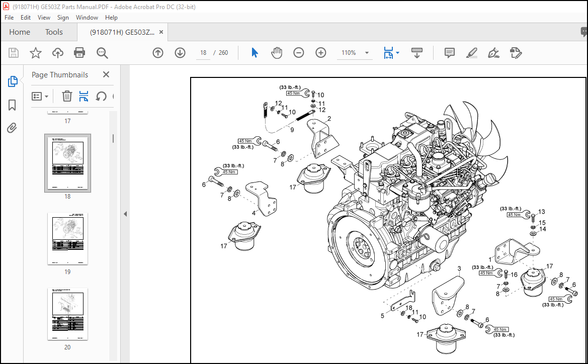
Engine Mounts…………………………………….14
Cylinder Head, Valve Cover………………….16
Cylinder Block…………………………………….17
Seal, Crankshaft…………………………………..18
Oil Pan ……………………………………………….20
Camshaft …………………………………………….22
Crankshaft, Piston………………………………..24
Lubrication………………………………………….26
Cooling System……………………………………28
Fuel Injection System …………………………..30
Intake Manifold …………………………………..32
Engine Air Filter ………………………………….34
Exhaust Components ……………………………37
Fuel Tank……………………………………………38
Fuel Supply…………………………………………40
Throttle Lever (Cab and Canopy)…………..42
Throttle Lever (Canopy) ……………………….44
Auto-Idle Kit (option)…………………………..45
Hydraulic Pump Drive………………………….46
Radiator………………………………………………47
Oil Cooler …………………………………………..50
Hydraulic Oil Tank ………………………………52
Hydraulic Pump External Components …..54
Hydraulic Pump Internal Components ……56
Turntable Drive Unit Installation……………57
Turntable Drive Unit…………………………….59
Drive Motor Installation …………………. 60-61
Drive Motor ………………………………….. 62-63
Control Valve Fittings ………………………….64
Control Valve Assembly……………………….66
Swivel Joint ………………………………………..67
Joysticks……………………………………………..68
Travel Pilot Valve………………………………..70
Travel Pilot Valve………………………………..71
Auxiliary Hydraulics Pilot Valve …….. 72-73
Dozer Blade Valve…………………………. 74-75
Selection Valve……………………………………76
Proportional Valve (Option) ………………….77
ISO/SAE Valve……………………………………78
Valve Block ………………………………………..79
Distribution Block ……………………………….80
Hydraulic Pump Installation………………….81
Proportional Control (Option) ……………….83
Boom Installation ………………………………..84
Boom Cylinder ……………………………………85
Dipper Arm Installation………………………..87
Dipper Arm Cylinder……………………………88
Bucket Installation……………………………….89
Bucket Cylinder…………………………………..90
Boom Offset Cylinder Installation …… 91-93
Boom Offset Cylinder ……………………. 94-95
Dozer Blade Installation …………………. 96-98
Dozer Blade Cylinder …………………… 99-100
Auxiliary Hydraulics Installation …. 101-102
ISO/SAE Valve Installation…………………104
Pilot Pressure Hoses …………………… 105-106
Hydraulic Tank Hoses ………………… 107-108
Dashboard (Cab)………………………… 110-111
Dashboard (Canopy)…………………… 113-114
Radio (Option)…………………………………..115
Battery ……………………………………………..116
Relay Box …………………………………………118
Boom Work Light………………………………120
Cab Work Light Kit (Option) ………………122
Wire Harness – Chassis, Engine …………..123
Wire Harness – Switch ………………… 126-127
Wire Harness – Armrest ………………. 129-130
Wire Harness – Work Light – Front
(Option) ………………………………………….131
Wire Harness – Roof (Cab)………………….133
Wire Harness – Auto-Idle (Option)……….136
Wire Harness – Proportional Control
(Option) ………………………………………….137
Chassis ……………………………………………..138
Rubber Track …………………………………….139
Steel Track (Option) …………………………..140
Undercarriage, Rubber Track ………………141
Undercarriage, Steel Track (Option) …….142
Track Tensioner, Rubber Track……. 143-144
Track Tensioner, Steel Track (Option)147-148
Dozer Blade ………………………………………149
Lubrication………………………………………..150
Counterweight …………………………………..151
Counterweight (Option)………………………153
Hood ………………………………………………..154
Tank Cover ……………………………………….157
Partition Wall…………………………………….158
Chassis Cover ……………………………………160
Isolation Mats ……………………………………162
Boom ……………………………………………….164
918071/HP0712 II Printed in U.S.A.
TABLE OF CONTENTS
Dipper Arm – Short…………………………….167
Dipper Arm – Long (Option) ……………….169
Undercarriage Cover…………………………..171
Cab Mounting ……………………………………172
Cab Mounting ……………………………………173
Cab Frame…………………………………..174-183
Canopy Frame……………………………..184-185
Cab Door…………………………………………..186
Windshield………………………………….187-188
Cab Windows ……………………………..192-193
Canopy Rear Window ………………………..194
Cab Mats…………………………………………..195
Cab Trim…………………………………….196-196
Mirrors (Option) ………………………….198-199
Rotating Beacon (Option)……………..200-201
Operator’s Seat ………………………………….202
Operator’s Seat ………………………………….204
Joystick Consoles ………………………………206
Heater……………………………………………….208
Air Conditioning Installation (Option) ….210
Air Conditioning (Option) …………………..213
Air Conditioning Compressor (Option)…214
Horn …………………………………………………216
Tool Kit, Grease Gun………………………….217
Numerical Index ………………………………..274
More products