$30
GEHL Compact Excavators 802 Parts Manual(918043) – PDF DOWNLOAD
GEHL Compact Excavators 802 Parts Manual(918043) – PDF DOWNLOAD
IMAGES PREVIEW OF THE MANUAL:
DESCRIPTION:
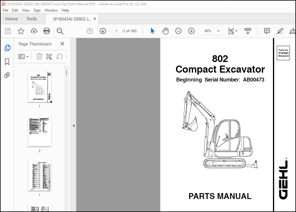
GEHL Compact Excavators 802 Parts Manual(918043) – PDF DOWNLOAD
Beginning Serial Number: AB00473
Introduction:
- When ordering service parts, please specify the correct part number, full description, quantity required, the unit model number, and serial number. For your safety and continued proper operation, use only genuine GEHL service parts.
- The model and serial number for this unit can be found on a tag located on a panel on the front of the cabin.
- “Right” and “left” are determined from a position sitting on the seat and facing forward. From this position, the cab is on the “left” and the hydraulic valve compartment is on the “right.”
- GEHL Company reserves the right to make changes or improvements in the design or construction of any part of the unit without incurring the obligation to install such changes on any previously delivered units.
- Refer to the abbreviations table located on this page for the various fastener descriptions. Standard attaching hardware torque values are also provided on the inside back cover. Metric torque values shown in the illustrations are in Newton-meters and can be converted to foot-pounds by multiplying by 0.738.
- In the exploded view parts list, Reference Numbers may have additional information following the Reference Number.
- Unless otherwise specified, all Cap Screws or Bolts are Grade 5, cadmium or zinc plated; Hexagon Nuts for Grade 5 Screws or Bolts are Grade B; Hexagon Nuts for other Screws or Bolts are Grade A.
General Information:
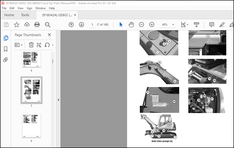
- Decal location information is provided to assist in the proper selection and application of new decals, in the event the original decals become damaged or the machine is repainted. Refer to the listing for the illustration reference number, part number, description, and quantity of each decal provided in the kit. Refer to the appropriate illustrations for replacement locations.
- To ensure proper selection of the correct replacement decals, compare all of the various close-up location drawings to your machine before starting to refinish the unit. Then circle each shown decal (applicable to your machine) while checking off its part number in the listing. After you have verified all the decals needed for replacement, place any extra unnecessary decals aside for disposal.
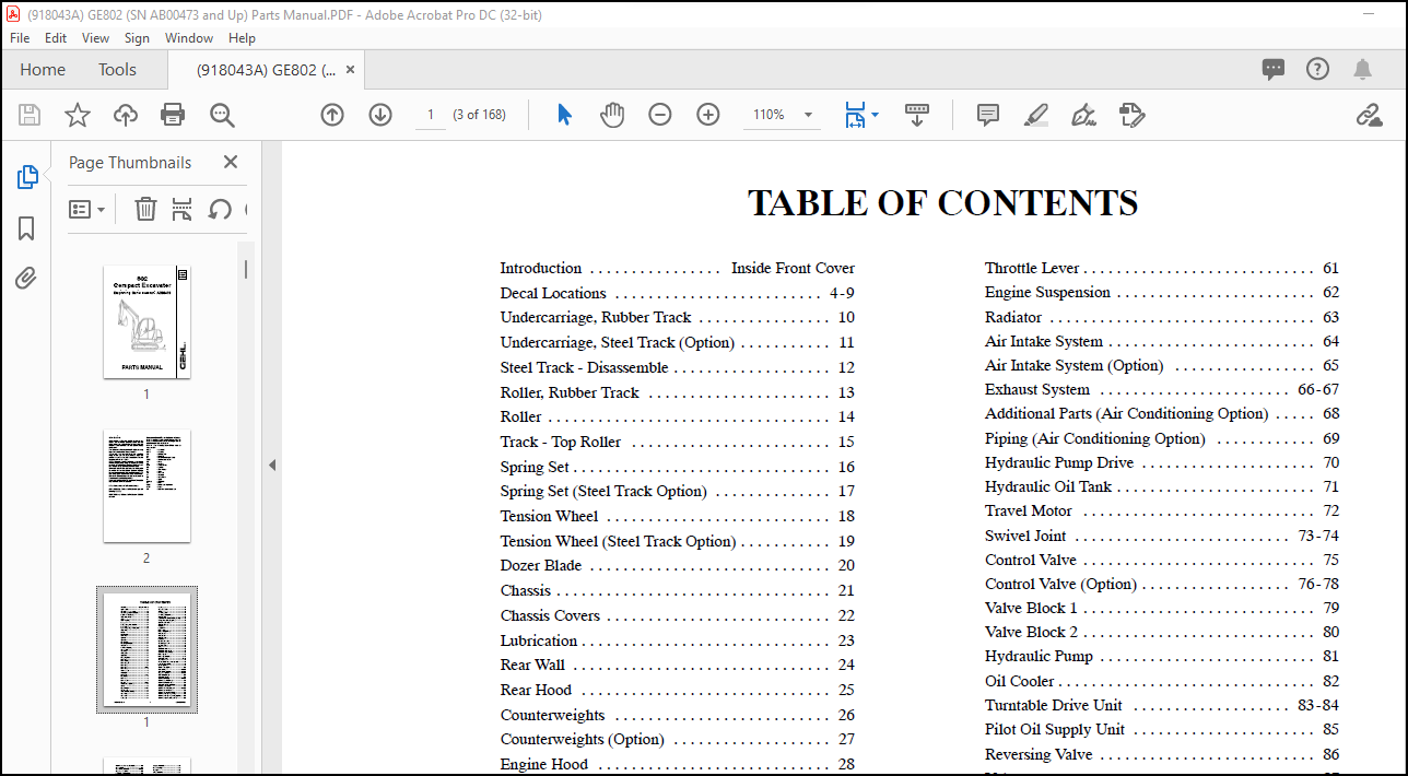
TABLE OF CONTENTS:
GEHL Compact Excavators 802 Parts Manual(918043) – PDF DOWNLOAD
Introduction . . . . . . . . . . . . . . . . Inside Front Cover
Decal Locations . . . . . . . . . . . . . . . . . . . . . . . . . 4-9
Undercarriage, Rubber Track . . . . . . . . . . . . . . . . 10
Undercarriage, Steel Track (Option) . . . . . . . . . . . 11
Steel Track – Disassemble . . . . . . . . . . . . . . . . . . . 12
Roller, Rubber Track . . . . . . . . . . . . . . . . . . . . . . 13
Roller . . . . . . . . . . . . . . . . . . . . . . . . . . . . . . . . . . 14
Track – Top Roller . . . . . . . . . . . . . . . . . . . . . . . . 15
Spring Set . . . . . . . . . . . . . . . . . . . . . . . . . . . . . . . 16
Spring Set (Steel Track Option) . . . . . . . . . . . . . . 17
Tension Wheel . . . . . . . . . . . . . . . . . . . . . . . . . . . 18
Tension Wheel (Steel Track Option) . . . . . . . . . . . 19
Dozer Blade . . . . . . . . . . . . . . . . . . . . . . . . . . . . . 20
Chassis . . . . . . . . . . . . . . . . . . . . . . . . . . . . . . . . . 21
Chassis Covers . . . . . . . . . . . . . . . . . . . . . . . . . . . 22
Lubrication . . . . . . . . . . . . . . . . . . . . . . . . . . . . . . 23
Rear Wall . . . . . . . . . . . . . . . . . . . . . . . . . . . . . . . 24
Rear Hood . . . . . . . . . . . . . . . . . . . . . . . . . . . . . . 25
Counterweights . . . . . . . . . . . . . . . . . . . . . . . . . . 26
Counterweights (Option) . . . . . . . . . . . . . . . . . . . 27
Engine Hood . . . . . . . . . . . . . . . . . . . . . . . . . . . . 28
Tool Box, Hose Cover . . . . . . . . . . . . . . . . . . . . . 29
Valve Bracket . . . . . . . . . . . . . . . . . . . . . . . . . . . . 30
Valve Cover . . . . . . . . . . . . . . . . . . . . . . . . . . . . . 31
Lifting Boom . . . . . . . . . . . . . . . . . . . . . . . . . . . . 32
Dipper Arm . . . . . . . . . . . . . . . . . . . . . . . . . . . . . 33
Connecting Links . . . . . . . . . . . . . . . . . . . . . . . . . 34
Cabin Frame 1 . . . . . . . . . . . . . . . . . . . . . . . . . . . 35
Cabin Mounting . . . . . . . . . . . . . . . . . . . . . . . . . . 36
Cabin Frame 1A . . . . . . . . . . . . . . . . . . . . . . . . . . 37
Cabin Frame 2 . . . . . . . . . . . . . . . . . . . . . . . . . . . 38
Cabin Frame 3 . . . . . . . . . . . . . . . . . . . . . . . . 39-40
Cabin Frame 4 . . . . . . . . . . . . . . . . . . . . . . . . . . . 41
Main Harnesses . . . . . . . . . . . . . . . . . . . . . . . . . . 42
Windshield . . . . . . . . . . . . . . . . . . . . . . . . . . . . . . 43
Cabin Windows . . . . . . . . . . . . . . . . . . . . . . . 44-46
Side Window . . . . . . . . . . . . . . . . . . . . . . . . . . . . 47
Cabin Door . . . . . . . . . . . . . . . . . . . . . . . . . . . . . . 48
Cabin Door 1A . . . . . . . . . . . . . . . . . . . . . . . . . . . 49
Covering . . . . . . . . . . . . . . . . . . . . . . . . . . . . 50-51
Rotating Beacon (Option) . . . . . . . . . . . . . . . . . . . 52
Heater . . . . . . . . . . . . . . . . . . . . . . . . . . . . . . . . . . 53
Operator’s Seat . . . . . . . . . . . . . . . . . . . . . . . . 54-55
Mounting Kit . . . . . . . . . . . . . . . . . . . . . . . . . . . . 56
Air Conditioning (Option) . . . . . . . . . . . . . . . . . . 57
Diesel Engine . . . . . . . . . . . . . . . . . . . . . . . . . . . . 58
Diesel Tank . . . . . . . . . . . . . . . . . . . . . . . . . . . . . . 59
Fuel Supply . . . . . . . . . . . . . . . . . . . . . . . . . . . . . 60
Throttle Lever . . . . . . . . . . . . . . . . . . . . . . . . . . . . 61
Engine Suspension . . . . . . . . . . . . . . . . . . . . . . . . 62
Radiator . . . . . . . . . . . . . . . . . . . . . . . . . . . . . . . . 63
Air Intake System . . . . . . . . . . . . . . . . . . . . . . . . . 64
Air Intake System (Option) . . . . . . . . . . . . . . . . . 65
Exhaust System . . . . . . . . . . . . . . . . . . . . . . . 66-67
Additional Parts (Air Conditioning Option) . . . . . 68
Piping (Air Conditioning Option) . . . . . . . . . . . . 69
Hydraulic Pump Drive . . . . . . . . . . . . . . . . . . . . . 70
Hydraulic Oil Tank . . . . . . . . . . . . . . . . . . . . . . . . 71
Travel Motor . . . . . . . . . . . . . . . . . . . . . . . . . . . . 72
Swivel Joint . . . . . . . . . . . . . . . . . . . . . . . . . . 73-74
Control Valve . . . . . . . . . . . . . . . . . . . . . . . . . . . . 75
Control Valve (Option) . . . . . . . . . . . . . . . . . . 76-78
Valve Block 1 . . . . . . . . . . . . . . . . . . . . . . . . . . . . 79
Valve Block 2 . . . . . . . . . . . . . . . . . . . . . . . . . . . . 80
Hydraulic Pump . . . . . . . . . . . . . . . . . . . . . . . . . . 81
Oil Cooler . . . . . . . . . . . . . . . . . . . . . . . . . . . . . . . 82
Turntable Drive Unit . . . . . . . . . . . . . . . . . . . 83-84
Pilot Oil Supply Unit . . . . . . . . . . . . . . . . . . . . . . 85
Reversing Valve . . . . . . . . . . . . . . . . . . . . . . . . . . 86
Valve . . . . . . . . . . . . . . . . . . . . . . . . . . . . . . . . . . 87
Distribution Block , Large . . . . . . . . . . . . . . . . . . 88
Distribution Block, Small . . . . . . . . . . . . . . . . . . . 89
Distribution Block (Option) . . . . . . . . . . . . . . . . . 90
Control Levers . . . . . . . . . . . . . . . . . . . . . . . . . . . 91
Control Levers (Option) . . . . . . . . . . . . . . . . . 92-93
Dozer Blade Valve . . . . . . . . . . . . . . . . . . . . . 94-95
Pilot Valve, Travel . . . . . . . . . . . . . . . . . . . . . . . . 96
Pilot Op. Check Valves Aux. Hydraulic . . . . . . . . 97
Solenoid Valve (Option) . . . . . . . . . . . . . . . . . . . . 98
4/3 Valve (Option) . . . . . . . . . . . . . . . . . . . . . . . . 99
ISO/SAE Valve (Option) . . . . . . . . . . . . . . . . . . 100
Boom Cylinder . . . . . . . . . . . . . . . . . . . . . . 101-102
Boom Cylinder (Option) . . . . . . . . . . . . . . 103-104
Dipper Arm Cylinder . . . . . . . . . . . . . . . . . 105-106
Boom Offset Cylinder . . . . . . . . . . . . . . . . . . . . 107
Dozer Blade Cylinder . . . . . . . . . . . . . . . . . . . . . 108
Installation Oil Cooler . . . . . . . . . . . . . . . . 109-110
Installation Hydraulic Pump . . . . . . . . . . . . . . . . 111
Installation Orientation Gear . . . . . . . . . . . . . . . . 112
Dozer Blade Cylinder Installation . . . . . . . . . . . . 113
Travel Motor Installation . . . . . . . . . . . . . . . . . . 114
Installation Turntable Drive Unit . . . . . . . . 115-116
Installation Control Levers . . . . . . . . . . . . . . . . . 117
Installation Control Levers (Option) . . . . . . . . . . 118
Installation Pilot Op. Check Valves . . . . . . . . . . 119
Installation Pilot Op. Check Valves (Option) . . . 120
Installation Pressure Holding Valves . . . . . . . . . . 121
918043/BP0703 2 Printed in U.S.A.
Installation Auxilary Function (Option) . . . . . . . 122
Boom Installation . . . . . . . . . . . . . . . . . . . . . . . . 123
Boom Cylinder Installation . . . . . . . . . . . . 124-125
Dipper Arm Installation . . . . . . . . . . . . . . . . . . . 126
3. Hydraulic Circuit (Option) . . . . . . . . . . . . . . . 127
Pilot Control (Option) . . . . . . . . . . . . . . . . 128-129
Engine Wire Harness . . . . . . . . . . . . . . . . . . . . . 130
Armrest – Harness Wiring Right . . . . . . . . . 131-132
Armrest – Harness Wiring Left . . . . . . . . . . 133-134
Armrest – Harness Wiring Left (Option) . . . . . . . 135
Chassis Wire Harness . . . . . . . . . . . . . . . . . . . . . 136
Armrest – Harness Wiring Right (Option) . . 137-138
Relay Box . . . . . . . . . . . . . . . . . . . . . . . . . . . . . 139
Relay Box Installation . . . . . . . . . . . . . . . . . . . . 140
Chassis Headlight . . . . . . . . . . . . . . . . . . . . . . . . 141
Headlights . . . . . . . . . . . . . . . . . . . . . . . . . . . . . 142
Battery Installation . . . . . . . . . . . . . . . . . . . . . . . 143
Horn . . . . . . . . . . . . . . . . . . . . . . . . . . . . . . . . . . 144
Armrest – Harness Wiring Right . . . . . . . . . . . . . 145
Tool Kit . . . . . . . . . . . . . . . . . . . . . . . . . . . . . . . 146
Index . . . . . . . . . . . . . . . . . . . . . . . . . . . . . 147-148
Numerical Index . . . . . . . . . . . . . . . . . . . . . 149-162
Notes . . . . . . . . . . . . . . . . . . . . . . . . . . . . . . . . . 163
Hydraulic Fitting Data . . . . . . . . . . . . . . . . . . . . 164
Torque Chart . . . . . . . . . . . . . . . . Inside Rear Cover
More products