$25
Gehl CT5-16 CT5-16 Turbo Telescopic Handler Operator’s Manual 913225 – PDF DOWNLOAD
Gehl CT5-16 CT5-16 Turbo Telescopic Handler Operator’s Manual 913225 – PDF DOWNLOAD
FILE DETAILS:
Gehl CT5-16 CT5-16 Turbo Telescopic Handler Operator’s Manual 913225 – PDF DOWNLOAD
Language : English
Pages : 98
Downloadable : Yes
File Type : PDF
Size: 5.03 MB
IMAGES PREVIEW OF THE MANUAL:
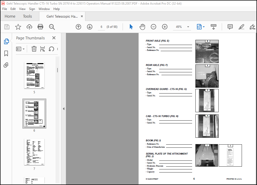
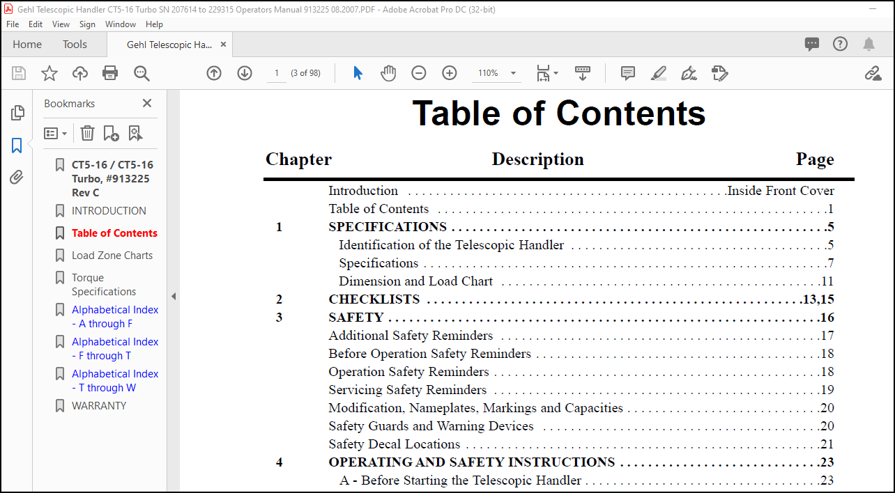
TABLE OF CONTENTS:
Gehl CT5-16 CT5-16 Turbo Telescopic Handler Operator’s Manual 913225 – PDF DOWNLOAD
Introduction Inside Front Cover
Table of Contents 1
1 SPECIFICATIONS 5
Identification of the Telescopic Handler 5
Specifications 7
Dimension and Load Chart 11
2 CHECKLISTS 13,15
3 SAFETY 16
Additional Safety Reminders 17
Before Operation Safety Reminders 18
Operation Safety Reminders 18
Servicing Safety Reminders 19
Modification, Nameplates, Markings and Capacities 20
Safety Guards and Warning Devices 20
Safety Decal Locations 21
4 OPERATING AND SAFETY INSTRUCTIONS 23
A – Before Starting the Telescopic Handler 23
B – Operator Instructions 23
C – Enviroment 23
D – Visibility 24
E – Starting the Telescopic Handler 24
F – Operating the Telescopic Handler 26
G – Stopping the Telescopic Handler 26
H – Driving the Telescopic Handler on a Public Highway 27
I – Driving the Telescopic Handler with a Front-Mounted Attachment 27
J – Operating the Telescopic Handler with a Trailer 27
Instructions for Handling a Load 28
K – Choice of Attachments 28
L – Mass and Center-of-Gravity of Load 28
M – Transverse Attitude of the Telescopic Handler 28
N – Picking Up a Load on the Ground 29
O – Picking Up a High Load 29
P – Setting Down a High Load 30
Q – Suspended Loads 31
– Guidelines for “FREE RIGGING/SUSPENDED LOADS” 31
5 INSTRUMENTS AND CONTROLS 32
Description 33
1 – Operator’s Seat 34
2 – Seat Belt 36
3 – Control and Signal Lamp Panel 36
913225/CP0807 2 PRINTED IN U S A
Chapter Description Page
4 – Boom Mounted Work Lights (Option) 37
5 – Switch Panel 37
6 – Light Switch, Horn and Indicator Switch 37
7 – Ignition Switch 37
8 – Brake Fluid Reservoir and Windshield Washer Access Panel 38
9 – Brake Fluid Reservoir 38
10 – Windshield Washer Reservoir 38
11 – Fuse and Relay Access Panel 38
12 – Fuses and Relays 38
13 – Cab Interior Light 39
14 – Accelerator Pedal 39
15 – Service Brake Pedal and Transmission Cut-off 39
16 – Forward/Reverse Lever 39
17 – Parking Brake Lever 40
18 – Steering Mode Selection 40
19 – Hydraulic Controls 41
20 – Load Charts 42
21 – Heater Controls (CT5-16 Turbo) 42
21 – Heater and Air Conditioner Controls (CT5-16 Turbo) 42
22 – Cab Air Filters (CT5-16 Turbo) 43
23 – Windshield Defroster (CT5-16 Turbo) 43
24 – Heater Vents (CT5-16 Turbo) 43
25 – Door Lock (CT5-16 Turbo) 43
26 – Locking Handle for Upper Half Door (CT5-16 Turbo) 43
27 – Releasing Button for Upper Half Door (CT5-16 Turbo) 44
28 – Handle for Rear Window Opening 44
29 – Manual Holder 44
30 – Front Lights 44
31 – Rear Lights 44
32 – Backup Alarm 44
33 – Inclinometer 44
34 – Engine Block Heater 44
35 – Radio 44
Tow Pin 45
A – Tow Pin 45
B – Trailer Electric Connector 45
6 MAINTENANCE 46
Gehl Original-Equipment Service Parts 46
Filter Cartridges and Belts 47
Lubricants and Fuel 48
Maintenance Instructions 49
General Instructions 49
Maintenance 49
PRINTED IN U S A 3 913225/CP0807
Chapter Description Page
Lubricant and Fuel Levels 49
Hydraulic Systems 49
Electrical Systems 49
Welding 49
Washing the Telescopic Handler 50
Storage Instructions 50
Preparing the Telescopic Handler 50
Protecting the Engine 50
Protecting the Telescopic Handler 51
Returning the Telescopic Handler into Service 51
Towing the Telescopic Handler 51
Lifting the Telescopic Handler 52
Loading the Telescopic Handler on a Trailer 52
Loading the Telescopic Handler 52
Tying Down the Telescopic Handler 52
Service Schedule 54
A – Daily or Every 10 Hours of Service 56
B – Every 50 Hours of Service 58
C – Every 250 Hours of Service 62
D – Every 500 Hours of Service 64
E – Every 1000 Hours of Service 68
F – Every 2000 Hours of Service 71
G – Periodic Maintenance 72
H – Every Two Years 74
7 DECALS 75
General Information 75
New Decal Application 75
Decal Locations 76
8 ATTACHMENTS 79
Introduction 79
Installing Attachments 80
A – Attachment w/o Hydraulics and Manual Locking Device 80
B – Hydraulic Attachment and Manual Locking Device 80
C – Attachment w/o Hydraulics and with Hydraulic Locking Device (Option) 81
D – Hydraulic Attachment and Hydraulic Locking Device (Option) 82
E – Attachment w/o Hydraulics and w/ Hydraulic Device (Tri-Function Joystick) 83
F – Hydraulic Attachment and Hydraulic Locking Device (Tri-Function Joystick) 83
G – Hydraulic Attachment and Manual Locking Device (Tri-Function Joystick) 84
Technical Specifications of Attachments 86
Load Zone Charts 90
Torque Specifications 91
Index 92
Warranty Inside Back Cover
More products