$38
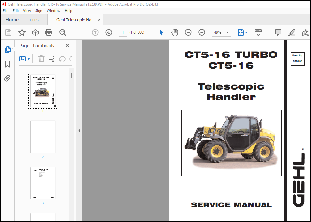
Gehl CT5-16 TURBO CT5-16 Telescopic Handler SERVICE MANUAL(913239) – PDF DOWNLOAD
Gehl CT5-16 TURBO CT5-16 Telescopic Handler SERVICE MANUAL(913239) – PDF DOWNLOAD
IMAGES PREVIEW OF THE MANUAL:
DESCRIPTION:
Gehl CT5-16 TURBO CT5-16 Telescopic Handler SERVICE MANUAL(913239) – PDF DOWNLOAD
General Information
Engine Description
- When you are ordering new parts, refer to the engine identification number in order to receive the correct parts. Refer to the Operation and Maintenance Manual, “Product Identification Information” for the correct numbers for your engine. The engine cylinders are arranged in-line. The engines are controlled by a mechanically governed fuel injection pump.
- The cylinder head assembly has one inlet valve and one exhaust valve for each cylinder. Each valve has one valve spring. The pistons have two compression rings and an oil control ring. It is important to ensure the correct piston height so that the piston does not contact the cylinder head.
- The correct piston height also ensures the efficient combustion of fuel. The 1104 engine crankshaft has five main journals. End play is controlled by thrust washers that are located on both sides of the center main bearing.
- The 1103 engine crankshaft has four main journals. End play is controlled by thrust washers that are located on both sides of the number three main bearing. The timing case has a hole that corresponds with a hole in the crankshaft. Use an alignment pin to find TC.
- The camshaft gear has a timing hole that corresponds with a timing hole in the timing case. The timing holes ensure that the camshaft and the crankshaft are in time with each other. The crankshaft gear rotates the idler gear. The idler gear rotates the camshaft gear and the fuel injection pump gear. The idler gear for the engine oil pump is rotated by the crankshaft gear.
- This idler rotates the engine oil pump. The fuel injection pump is a gear-driven pump that is mounted to the back of the front housing. The fuel transfer pump is electrically operated. The fuel transfer pump has an integral fuel filter. The fuel transfer pump is usually located on the left hand side of the cylinder block.
- Some applications may have the fuel transfer pump and the water separator (if equipped) relocated off the engine. The oil pump is driven by an idler gear. The engine oil pump sends lubricating oil to the main oil gallery. The oil relief valve is internal to the oil pump. Coolant from the bottom of the radiator passes through the water pump. The water pump is driven by the idler gear.
TABLE OF CONTENTS:
Gehl CT5-16 TURBO CT5-16 Telescopic Handler SERVICE MANUAL(913239) – PDF DOWNLOAD
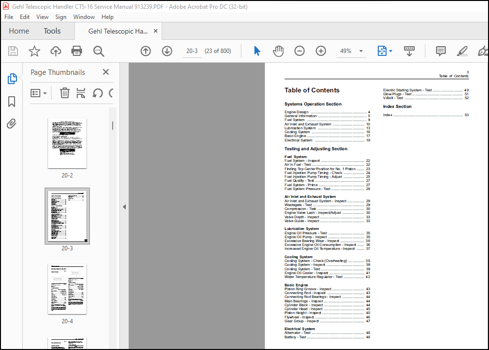
Systems Operation Section
Engine Design ………………………………………………. 4
General Information ………………………………………… 5
Fuel System ………………………………………………….. 9
Air Inlet and Exhaust System …………………………. 10
Lubrication System ………………………………………. 13
Cooling System ……………………………………………. 16
Basic Engine ………………………………………………… 17
Electrical System …………………………………………. 19
Testing and Adjusting Section
Fuel System
Fuel System – Inspect ……………………………………. 22
Air in Fuel – Test ……………………………………………. 22
Finding Top Center Position for No. 1 Piston …….. 23
Fuel Injection Pump Timing – Check ………………… 24
Fuel Injection Pump Timing – Adjust ………………… 25
Fuel Quality – Test …………………………………………. 27
Fuel System – Prime ……………………………………… 27
Fuel System Pressure – Test …………………………… 28
Air Inlet and Exhaust System
Air Inlet and Exhaust System – Inspect …………….. 29
Wastegate – Test …………………………………………… 29
Compression – Test ……………………………………….. 30
Engine Valve Lash – Inspect/Adjust …………………. 30
Valve Depth – Inspect …………………………………….. 33
Valve Guide – Inspect …………………………………….. 33
Lubrication System
Engine Oil Pressure – Test ……………………………… 35
Engine Oil Pump – Inspect ……………………………… 35
Excessive Bearing Wear – Inspect …………………… 36
Excessive Engine Oil Consumption – Inspect ……. 36
Increased Engine Oil Temperature – Inspect …….. 37
Cooling System
Cooling System – Check (Overheating) ……………. 38
Cooling System – Inspect ……………………………….. 39
Cooling System – Test ……………………………………. 39
Engine Oil Cooler – Inspect …………………………….. 41
Water Temperature Regulator – Test ………………… 42
Basic Engine
Piston Ring Groove – Inspect ………………………….. 43
Connecting Rod – Inspect ………………………………. 43
Connecting Rod Bearings – Inspect …………………. 44
Main Bearings – Inspect …………………………………. 44
Cylinder Block – Inspect …………………………………. 44
Cylinder Head – Inspect …………………………………. 45
Piston Height – Inspect …………………………………… 45
Flywheel – Inspect …………………………………………. 46
Gear Group – Inspect …………………………………….. 47
Electrical System
Alternator – Test ……………………………………………. 48
Battery – Test ………………………………………………… 48
Electric Starting System – Test ………………………… 49
Glow Plugs – Test ………………………………………….. 51
V-Belt – Test …………………………………………………. 52
Index Section
Index …………………………………………………………… 53
More products