$36
Gehl CTL60 Compact Track Loader Service Manual 908310 – PDF DOWNLOAD
Gehl CTL60 Compact Track Loader Service Manual 908310 – PDF DOWNLOAD
FILE DETAILS:
Gehl CTL60 Compact Track Loader Service Manual 908310 – PDF DOWNLOAD
Language : English
Pages : 755
Downloadable : Yes
File Type : PDF
Size: 38.5 MB
IMAGES PREVIEW OF THE MANUAL:
DESCRIPTION:
Gehl CTL60 Compact Track Loader Service Manual 908310 – PDF DOWNLOAD
FOREWORD:
This manual is intended for persons who engage in maintenance operations, and explains
procedures for disassembly and reassembly of the machine, check and maintenance procedures,
maintenance reference values, troubleshooting and outline specifications, etc. Please use this
manual as a reference in service activities to improve maintenance techniques.
Further, please be advised that items contained in this manual are subject to change without notice
due to design modifications, etc.
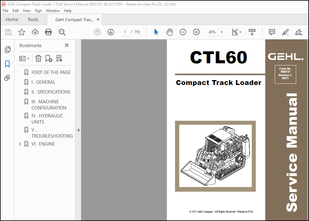
MACHINE FRONT AND REAR, LEFT AND RIGHT:
The end where the bucket is mounted is the front and the end with the travel motors is the rear.
Also the right and left sides of the operator when he is seated in the driver’s seat are the right and
left sides of the machine.
MACHINE SERIAL NUMBER:
The machine serial number is stamped on the identification plate. When sending reports and
inquiries, and when ordering parts, etc., be sure to include this number.
MANUAL CONTROL:
Information on those to whom this manual is distributed is recorded in the ledger in the section
in charge at this company, so please decide on a person to be in charge of it and control it. When
there are updates or additions, etc., we will notify the person in charge.
TABLE OF CONTENTS:
Gehl CTL60 Compact Track Loader Service Manual 908310 – PDF DOWNLOAD
FOOT OF THE PAGE…………………………………………………… 5
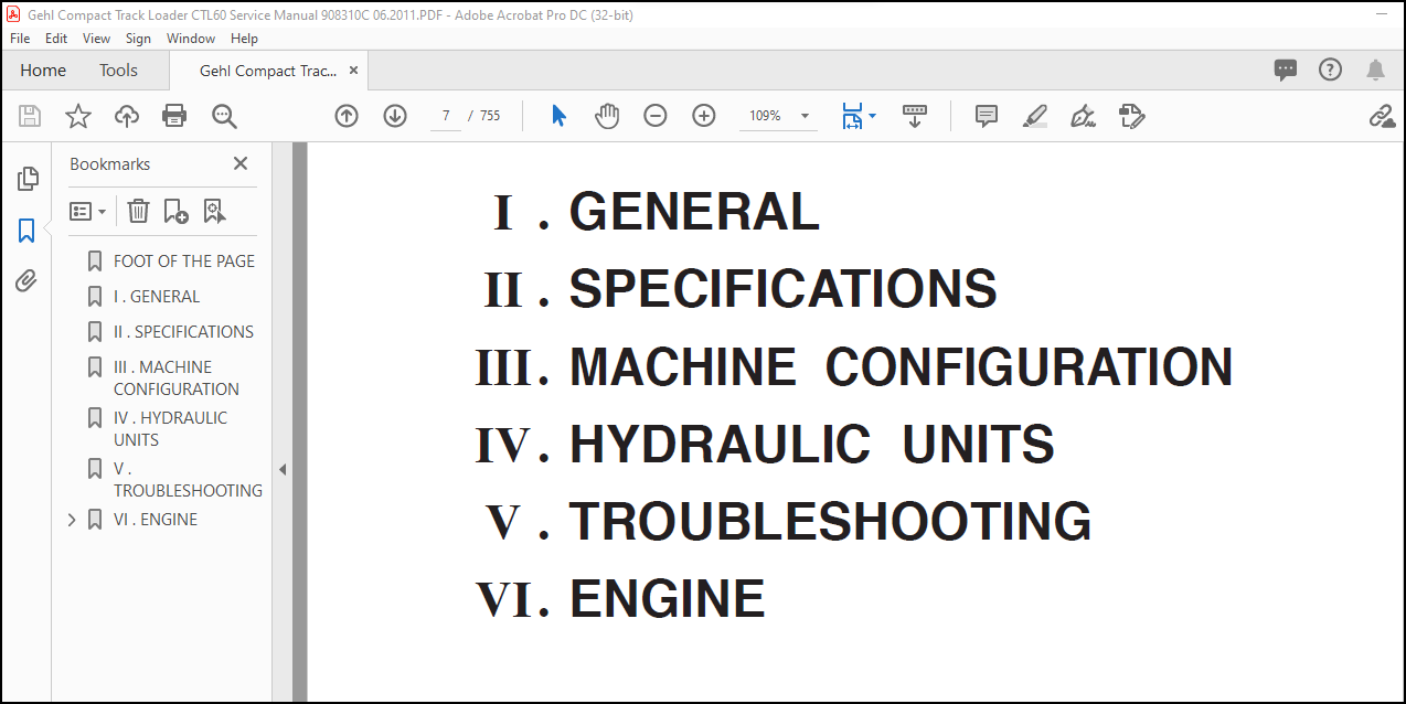
I . GENERAL……………………………………………………….. 9
II . SPECIFICATIONS………………………………………………… 23
III . MACHINE CONFIGURATION…………………………………………. 45
IV . HYDRAULIC UNITS………………………………………………..171
V . TROUBLESHOOTING…………………………………………………323
VI . ENGINE………………………………………………………..353
4TNE94/98/106 (T)……………………………………………….354
CONTENTS……………………………………………………362
3TNV/4TNV series………………………………………………..534
Cover………………………………………………………534
History of Revision………………………………………….535
PREFACE…………………………………………………….536
SAFETY LABELS……………………………………………….537
CONTENTS……………………………………………………545
1. General………………………………………………….550
1.1 Engine nomenclature…………………………………..550
1.2 Specifications……………………………………….550
1.3 Fuel oil, lubricating oil and cooling water……………..563
1.3.1 Fuel oil……………………………………….563
1.3.2 Lubricating oil…………………………………564
1.3.3 Cooling water…………………………………..565
1.4 Engine external views…………………………………566
1.5 Structural description………………………………..567
1.6 Exhaust gas emission regulation………………………..568
1.6.1 The emission standard in USA……………………..568
1.6.2 Engine identification……………………………569
1.6.3 Guarantee conditions for the EPA emission standard….570
2. Inspection and adjustment………………………………….572
2.1 Periodic maintenance schedule………………………….572
2.2 Periodic inspection and maintenance procedure……………573
2.2.1 Check before daily operation……………………..573
2.2.2 inspection after initial 50 hours operation………..575
2.2.3 Inspection every 50 hours………………………..578
2.2.4 Inspection every 250 hours or 3 months…………….582
2.2.5 Inspection every 500 hours or 6 months…………….585
2.2.6 Inspection every 1,000 hours or one year…………..587
2.2.7 Inspection every 2000 hours or 2 years…………….596
2.3 Adjusting the no-load maximum or minimum speed…………..600
2.4 Sensor inspection…………………………………….601
2.4.1 Oil pressure switch……………………………..601
2.4.2 Thermo switch…………………………………..601
2.5 Water leak check in cooling water system………………..601
2.6 Radiator cap inspection……………………………….602
2.7 Thermostat Inspection…………………………………602
2.8 Adjusting operation…………………………………..603
2.9 Long storage…………………………………………603
3. Troubleshooting…………………………………………..604
3.1 Preparation before troubleshooting……………………..604
3.2 Quick reference table for troubleshooting……………….605
3.3 Troubleshooting by measuring compression pressure………..608
4. Disassembly, inspection and reassembly of engines…………….610
4.1 Complete disassembly and reassembly…………………….610
4.1.1 Introduction……………………………………610
4.1.2 Special service tools……………………………611
4.1.3 Complete disassembly…………………………….616
4.1.4 Precautions before and during reassembly…………..620
4.1.5 Adjusting operation……………………………..620
4.2 Cylinder head: Disassembly, inspection and reassembly…….621
4.2.1 Components (2-valve cylinder head)………………..621
4.2.2 Disassembly procedure:…………………………..621
4.2.3 Reassembly procedure:……………………………622
4.2.4 Servicing points………………………………..623
4.2.5 Parts Inspection and measurement………………….627
4.2.6 Valve seat correction……………………………631
4.2.7 Valve guide replacement………………………….632
4.2.8 Valve stem seal replacement………………………633
4.3 Gear train and camshaft……………………………….634
4.3.1 Components……………………………………..634
4.3.2 Disassembly procedure:…………………………..634
4.3.3 Reassembly procedure:……………………………634
4.3.4 Servicing points………………………………..635
4.3.5 Parts inspection and measurement………………….638
4.3.6 Oil seal replacement (Gear case side)……………..640
4.3.7 Camshaft bushing replacement……………………..640
4.4 Cylinder block……………………………………….641
4.4.1 Components……………………………………..641
4.4.2 Disassembly procedure:…………………………..641
4.4.3 Reassembly procedure:……………………………641
4.4.4 Servicing points………………………………..642
4.4.5 Parts inspection and measurement………………….646
4.4.6 Cylinder bore correction…………………………657
4.4.7 Piston pin bushing replacement……………………658
4.4.8 Oil seal replacement (Flywheel housing side)……….658
5. Lubrication system………………………………………..659
5.1 Lubrication system diagram…………………………….659
5.2 Trochoid pump components………………………………660
5.3 Disassembly (Reverse the procedure below for assembly)……660
5.4 Servicing points……………………………………..660
5.5 Parts Inspection and measurement……………………….662
5.5.1 Trochoid pump inspection and measurement…………..662
5.6 Lube oil filter………………………………………664
5.6.1 Lube oil filter construction……………………..664
5.6.2 Lube oil filter replacement………………………664
6. Cooling system……………………………………………665
6.1 Cooling water system………………………………….665
6.2 Cooling water pump components………………………….665
6.3 Disassembly (Reverse the procedure below for assembly)……666
6.4 Servicing points……………………………………..666
7. Fuel injection pump / Governor……………………………..667
7.1 Introduction…………………………………………667
7.2 Fuel injection pump…………………………………..667
7.2.1 Fuel system diagram……………………………..667
7.2.2 External view and components……………………..668
7.2.3 Disassembly procedure:…………………………..668
7.2.4 Assembly procedure………………………………669
7.2.5 Servicing points………………………………..669
7.2.6 C.S.D. (Cold Start Device)……………………….670
8. Turbocharger: Disassembly, inspection and reassembly………….671
8.1 Structure and functions……………………………….671
8.1.1 Main specifications……………………………..671
8.1.2 Construction……………………………………671
8.1.3 Structural and functional outline…………………672
8.1.4 Components……………………………………..673
8.2 Service standards and tightening torque…………………674
8.2.1 Service standards……………………………….674
8.2.2 Tightening torque……………………………….675
8.3 Periodic inspection procedure………………………….676
8.3.1 Periodic inspection intervals…………………….676
8.3.2 Inspection procedure…………………………….677
8.3.3 Waste gate valve adjustment procedure……………..678
8.4 Disassembly procedure…………………………………680
8.4.1 Preparation for disassembly………………………680
8.4.2 Inspection before disassembly…………………….681
8.4.3 Disassembly…………………………………….681
8.5 Washing and inspection procedure……………………….683
8.5.1 Washing………………………………………..683
8.5.2 Inspection procedure…………………………….684
8.6 Reassembly procedure………………………………….687
8.6.1 Preparation for reassembly……………………….687
8.6.2 Reassembly……………………………………..687
8.7 Handling after disassembly and reassembly……………….690
8.7.1 Instructions for turbocharger installation…………690
8.8 Troubleshooting………………………………………691
8.8.1 Excessively exhaust smoke………………………..691
8.8.2 White smoke generation…………………………..691
8.8.3 Sudden oil decrease……………………………..692
8.8.4 Decrease in output………………………………692
8.8.5 Poor (slow) response (starting) of turbocharger…….692
8.8.6 Abnormal sound or vibration………………………692
9. Starting motror…………………………………………..693
9.1 For 4TNV94L/ 98………………………………………693
9.1.1 Specifications………………………………….693
9.1.2 Components……………………………………..694
9.1.3 Troubleshooting…………………………………695
9.1.4 Names of parts and disassembly procedure…………..696
9.1.5 Inspection and maintenance……………………….700
9.1.6 Service standards……………………………….705
9.1.7 Assembly……………………………………….706
9.1.8 Characteristic test……………………………..708
9.2 For 4TNV106 (T)………………………………………709
9.2.1 Specifications………………………………….709
9.2.2 Congiguration drawing……………………………709
9.2.3 Troubleshooting…………………………………710
9.2.4 Component names and disassembly procedure………….711
9.2.5 Disassembly procedure……………………………712
9.2.6 Inspection and maintenance……………………….720
9.2.7 Assembly……………………………………….726
9.2.8 Adjustment……………………………………..727
9.2.9 Service standards……………………………….728
9.3 For 3TNV82A to 3/4TNV88……………………………….729
9.3.1 Specifications………………………………….729
9.3.2 Characteristics…………………………………729
9.3.3 Disassembly drawing……………………………..730
9.3.4 Connecting diagram of a starting motor…………….730
10. Alternator………………………………………………731
10.1 The 40A alternator for 3TNV84 and other models………….731
10.1.1 Components…………………………………….731
10.1.2 Specifications…………………………………732
10.1.3 Wiring diagram…………………………………732
10.1.4 Standard output characteristics………………….733
10.1.5 Inspection…………………………………….733
10.1.6 Troubleshooting………………………………..734
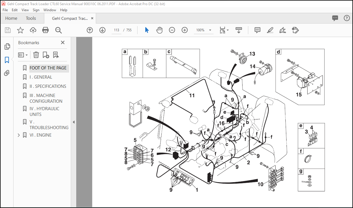
11. Electric wiring………………………………………….735
11.1 Electric wiring diagram………………………………735
11.2 Precaution on electric wiring…………………………736
11.2.1 Alternator…………………………………….736
11.2.2 Starter……………………………………….737
11.2.3 Current limiter………………………………..738
11.2.4 Section area and resistance of electric wire………739
12. Service standards………………………………………..740
12.1 Engine tuning……………………………………….740
12.2 Engine body…………………………………………742
12.2.1 Cylinder head………………………………….742
12.2.2 Gear train and camshaft…………………………745
12.2.3 Cylinder block…………………………………746
12.3 Lubricating oil system (Trochoid pump)…………………751
13. Tightening torque for bolts and nuts……………………….752
13.1 Tightening torques for main bolts and nuts…………….. 0
13.2 Tightening torques for standard bolts and nuts…………. 0
Back cover………………………………………………….754
More products