$36
Gehl CTL75 Compact Track Loader Service Manual 917342C – PDF DOWNLOAD
Gehl CTL75 Compact Track Loader Service Manual 917342C – PDF DOWNLOAD
FILE DETAILS:
Gehl CTL75 Compact Track Loader Service Manual 917342C – PDF DOWNLOAD
Language : English
Pages : 343
Downloadable : Yes
File Type : PDF
Size: 23.4 MB
IMAGES PREVIEW OF THE MANUAL:
DESCRIPTION:
Gehl CTL75 Compact Track Loader Service Manual 917342C – PDF DOWNLOAD
FOREWORD
This manual, which is written for engineers who service the machine, describes procedures for disassembly and assembly,
inspection and maintenance, and troubleshooting, as well as maintenance reference values and an outline of the specifications.
Refer to this manual during daily work to improve your services. Note that the information is subject to change without
notice due to design modifications made to the machine from time to time by the manufacturer.
Directional terms: front, rear, left, right
In this manual, the “front” refers to the end of the machine where the bucket is mounted, while the “rear” refers to the other
end where the travel motor is mounted. The “right” or “left” refers to the side viewed by a person sitting in the operator’s
seat.
Machine serial number
The machine serial number is stamped on the identification plate. Be sure to include this number when sending a report or
inquiry or when ordering parts.
Control of manual
Appoint a person in charge of keeping the manuals up to date in your company and inform us of the person’s name for our
records. Any revisions or additions to this manual will be sent to the person.
Symbols used in this manual
The symbols used in this manual have the following meanings.
TABLE OF CONTENTS:
Gehl CTL75 Compact Track Loader Service Manual 917342C – PDF DOWNLOAD
SAFETY……………………………………………………………………. 3
Safety alert symbol…………………………………………………….. 4
Safety precautions……………………………………………………… 5
Cautions when working…………………………………………………… 11
SERVICE DATA………………………………………………………………. 13
Dimensional drawing…………………………………………………….. 14
Specifications tables…………………………………………………… 15
Lubricant and Fuel chart………………………………………………… 18
Performance criteria……………………………………………………. 20
Tightening torque………………………………………………………. 28
Hydraulic circuit diagram……………………………………………….. 0
Electrical wiring diagram……………………………………………….. 33
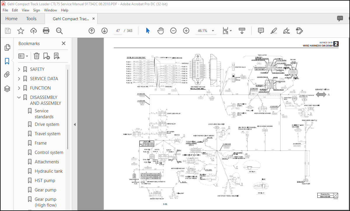
Wire harness diagram……………………………………………………. 35
FUNCTION………………………………………………………………….. 71
HST pump………………………………………………………………. 72
Gear pump……………………………………………………………… 75
Control valve………………………………………………………….. 76
Sub valve……………………………………………………………… 87
Pilot valve……………………………………………………………. 89
Proportional control solenoid valve………………………………………. 90
Cylinders……………………………………………………………… 91
Travel motor…………………………………………………………… 92
Proportional control equipment…………………………………………… 95
Air conditioner system………………………………………………….. 99
DISASSEMBLY AND ASSEMBLY…………………………………………………….121
Service standards……………………………………………………….122
Drive system……………………………………………………………124
Travel system…………………………………………………………..131
Frame………………………………………………………………….134
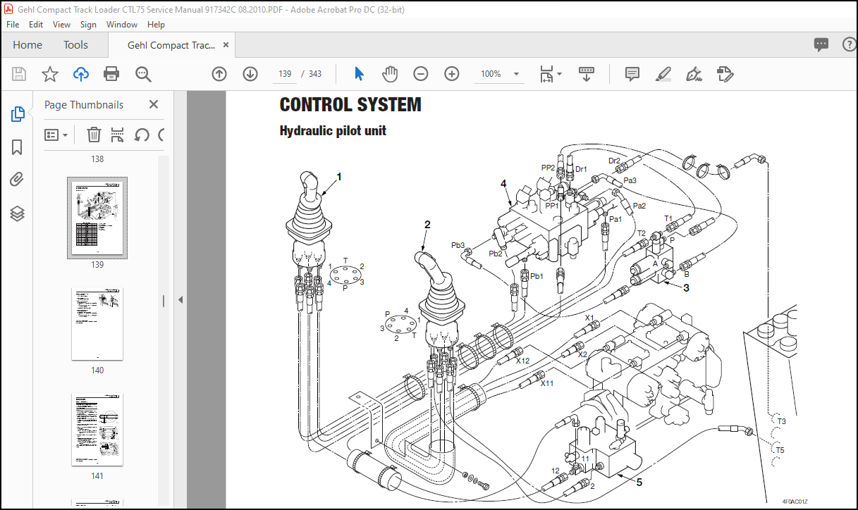
Control system………………………………………………………….139
Attachments…………………………………………………………….141
Hydraulic tank………………………………………………………….148
HST pump……………………………………………………………….150
Gear pump………………………………………………………………201
Gear pump (High flow)……………………………………………………206
Control valve…………………………………………………………..211
Control valve (High flow)………………………………………………..217
Sub valve………………………………………………………………221
Pilot valve…………………………………………………………….226
Proportional control solenoid valve……………………………………….233
Cylinders………………………………………………………………235
Travel motor……………………………………………………………249
TROUBLESHOOTING…………………………………………………………….271
Overall machine…………………………………………………………273
No operation is possible……………………………………………..273
All systems working, but insufficient power…………………………….276
Lift arm and bucket fail to move or are too slow………………………..278
Traveling………………………………………………………………279
Traveling fails……………………………………………………..279
Right or left travel speed decelerates and the machine veers to one side…..281
Operating temperature of the travel system is too high…………………..282
2nd speed travel is not possible………………………………………284
Lift arm……………………………………………………………….286
Arm cylinder fails…………………………………………………..286
Arm cylinder is slow or the power is insufficient……………………….288
When the control lever is pulled slowly, the lift arm drops once………….290
Spontaneous drop of the lift arm is too large…………………………..291
Bucket…………………………………………………………………292
Bucket cylinder fails to move…………………………………………292
Bucket cylinder is slow or the power is insufficient…………………….294
Spontaneous drop of the bucket is too large…………………………….296
Auxiliary hydraulics…………………………………………………….297
Proportional control is not possible…………………………………..297
HST pump……………………………………………………………….303
Gear pump………………………………………………………………305
Control valve…………………………………………………………..306
SUB valve………………………………………………………………308
Pilot valve…………………………………………………………….309
Proportional control solenoid valve……………………………………….310
Cylinders………………………………………………………………311
Travel motor……………………………………………………………312
Air conditioner…………………………………………………………314
More products