$21
Gehl FC7200 Flail Chopper Parts Manual(908009) – PDF DOWNLOAD
Gehl FC7200 Flail Chopper Parts Manual(908009) – PDF DOWNLOAD
FILE DETAILS:
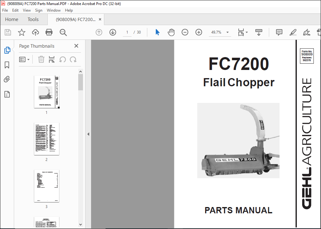
Gehl FC7200 Flail Chopper Parts Manual(908009) – PDF DOWNLOAD
Language : English
Pages : 30
Downloadable : Yes
File Type : PDF
Size: 632 KB
TABLE OF CONTENTS:
Gehl FC7200 Flail Chopper Parts Manual(908009) – PDF DOWNLOAD
Introduction Inside Front Cover
Table of Contents 1
Decal Locations 2-3
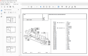
Frame, Axles & Lift Control 4-5
PTO & Drive 6-7
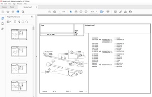
Cylinder, Conveyor & Drives 8-9
Blower-Cutter & Drive 10-11
Deflector, Cap & Controls 12
Transmissions 13
Hitchjacks 14-15
Universal Drives 16
Options & Accessories 17-19
Deflector Brace Kit 17
Trough Deflector Kit 18
Conveyor Cover Kit 18
3-Knife & Fan Kit 18
PTO High Pedestal Kit 18
1-Ft Vertical Extension 19
3-Ft Horizontal Extension 19
Hydraulic Lift Kit 19
Hydraulic Cylinder & Hose Kit 19
Service Kits 20-21
Alphabetical Index 22
Numerical Index 23-25
Standard Hardware Torque Specifications Inside Back Cover
DESCRIPTION:
Gehl FC7200 Flail Chopper Parts Manual(908009) – PDF DOWNLOAD
Introduction
- When ordering service parts, specify the correct part number, full description, quantity required, the unit model number and serial number.
- The model and serial number for this unit are stamped on a plate located on the left rear of the Main Frame adjacent to the Lift Control Crank.
- “Right” and “Left” are determined from a position standing at the rear of the unit facing the direction of travel. From this position, the Transmission and Drive are on the “Left” side. GEHL Company reserves the right to make changes or improvements in the design or construction of any part of the unit without incurring the obligation to install such changes on any previously delivered units.
- Refer to the abbreviations table located on this page for the various fastener descriptions. Standard attaching hardware torque values are also provided on the inside back cover.
- In the exploded view parts list, Reference Numbers may have additional information following the Reference Number. A Tear Drop symbol will indicate an application of a “wet” product such as oil, and the number inside the Tear Drop will correspond to the description in the Parts List
- Also, a number inside of a hexagon will be the torque value required, in foot pounds, on the associated Reference Number. Items shown in the parts list that do not have Reference Numbers are shown for reference purposes only and are NOT available for purchase. Unless otherwise specified, all Cap Screws or Bolts are Grade 5, cadmium or zinc plated; Hexagon Nuts for Grade 5 Screws or Bolts are Grade B; Hexagon Nuts for other Screws or Bolts are Grade A
IMAGES PREVIEW OF THE MANUAL:
More products