$26
Gehl Forage Harvesters CB860 CB865 Parts Manual(907506) – PDF DOWNLOAD
Gehl Forage Harvesters CB860 CB865 Parts Manual(907506) – PDF DOWNLOAD
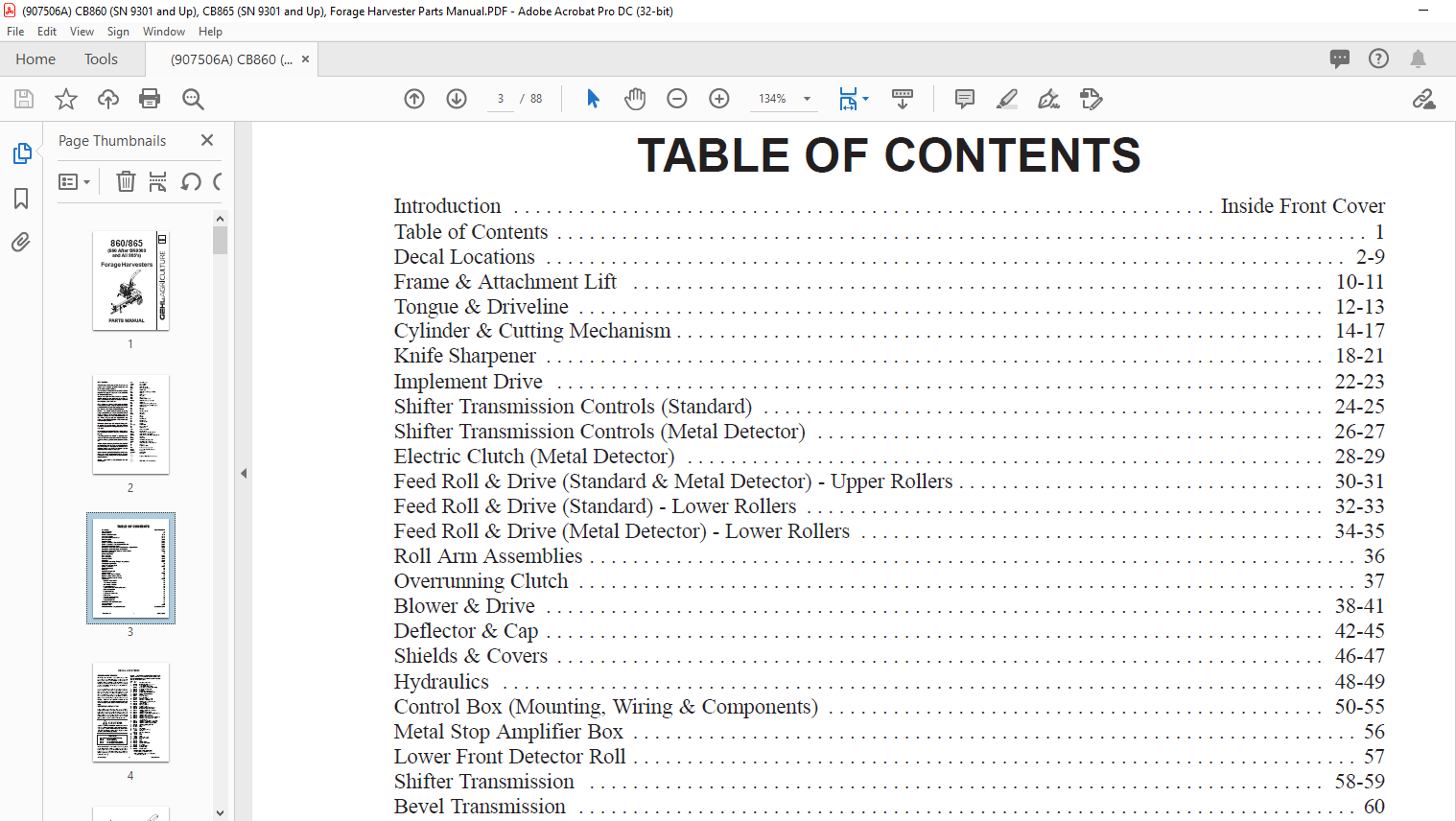
TABLE OF CONTENTS:
Gehl Forage Harvesters CB860 CB865 Parts Manual(907506) – PDF DOWNLOAD
Introduction Inside Front Cover
Table of Contents 1
Decal Locations 2-9
Frame & Attachment Lift 10-11
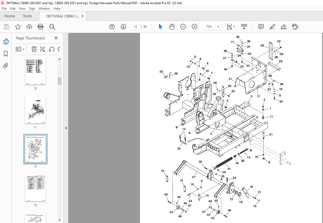
Tongue & Driveline 12-13
Cylinder & Cutting Mechanism 14-17
Knife Sharpener 18-21
Implement Drive 22-23
Shifter Transmission Controls (Standard) 24-25
Shifter Transmission Controls (Metal Detector) 26-27
Electric Clutch (Metal Detector) 28-29
Feed Roll & Drive (Standard & Metal Detector) – Upper Rollers 30-31
Feed Roll & Drive (Standard) – Lower Rollers 32-33
Feed Roll & Drive (Metal Detector) – Lower Rollers 34-35
Roll Arm Assemblies 36
Overrunning Clutch 37
Blower & Drive 38-41
Deflector & Cap 42-45
Shields & Covers 46-47
Hydraulics 48-49
Control Box (Mounting, Wiring & Components) 50-55
Metal Stop Amplifier Box 56
Lower Front Detector Roll 57
Shifter Transmission 58-59
Bevel Transmission 60
Hitchjack 61
Hydraulic Components 62
Universal Drives 63-65
Optional Single Axles & Wheels 66
Optional Tandem Axles & Wheels 67
Optional Flotation Axles & Wheels 68
Accessories 69-74
Hydraulic Hitch Control 69
1-Ft Vertical Extension 69
2-Ft Vertical Extension 69
6″ Vertical Extension 69
3-1/2-Ft Horizontal Deflector Extension 70
Deflector Tripod Kit 71
Selector Valve Kit 72
Lift Cylinder & Hose Kit 73
Safety Chain 73
Transport Lighting Package 73
Screen Mounting Kit 74
Square-hole Screens 74
Service Kits – Electrical Connectors 75
Alphabetical Index 76
Numerical Index 77-84
Standard Hardware Torque Specifications Inside Back Cover
DESCRIPTION:
Gehl Forage Harvesters CB860 CB865 Parts Manual(907506) – PDF DOWNLOAD
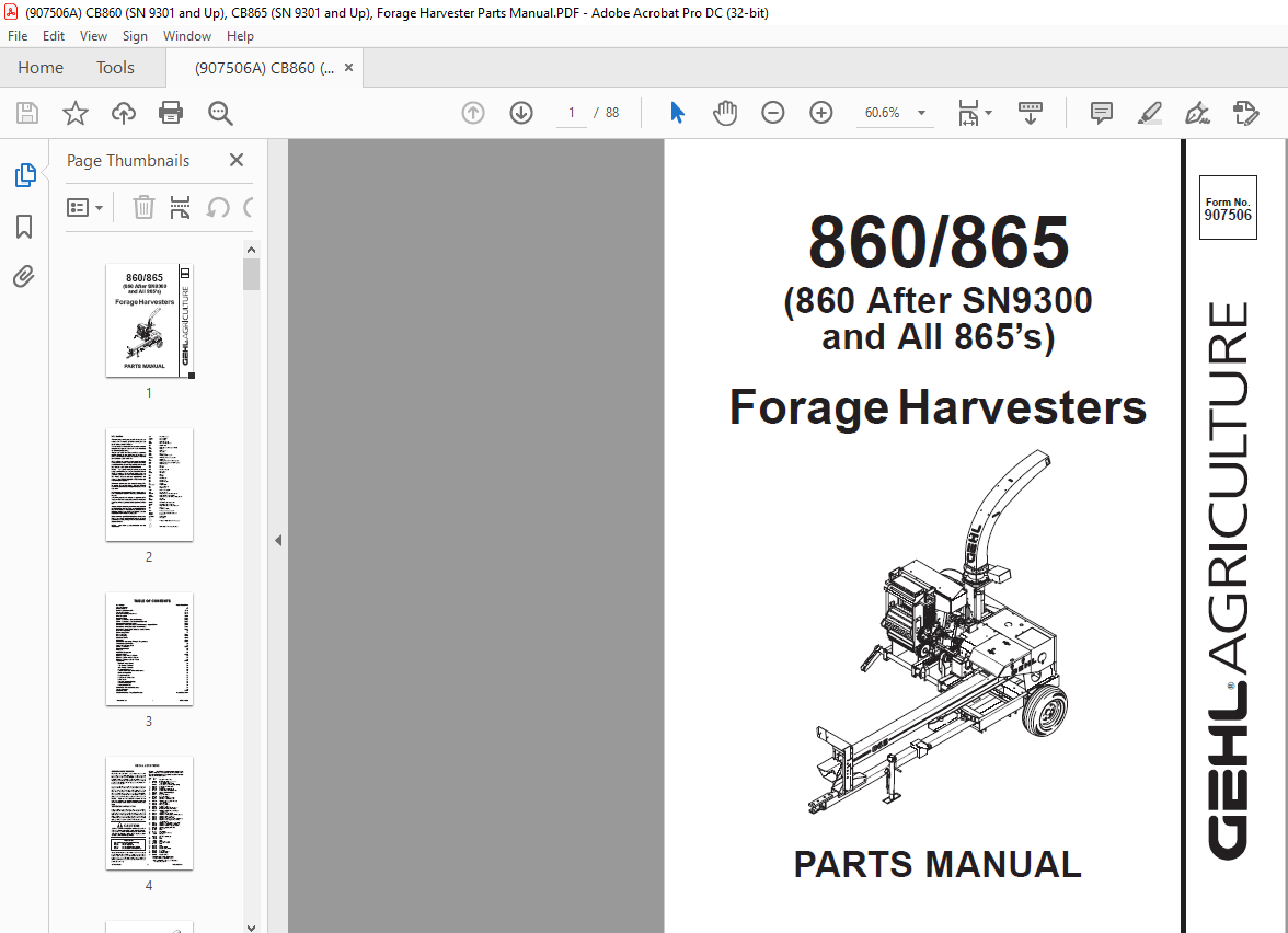
(860 After SN9300
and All 865’s)
Introduction
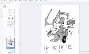
When ordering service parts, specify the correct part number, full description, quantity required, the unit model number and serial number.
- The model and serial number for this unit is on a plate located on the right side of the Main Frame adjacent to the Cylinder Shaft Bearing.
- “Right’’ and “Left’’ are determined from a position standing behind the unit and facing the direction of travel. From this position the Bevel Gearbox and Main Drive Shaft are on the “Left” side. GEHL Company reserves the right to make changes or improvements in the design or construction of any part of the unit without incurring the obligation to install such changes on any previously delivered units
GENERAL INFORMATION:
- Decal location information is provided to assist in the proper selection and application of new decals, in the event the original decals become damaged or the machine is repainted. Please refer to the listing for the illustration reference number, part number, description, and quantity of each decal provided in the kit. Refer to the appropriate illustrations for replacement locations.
- To ensure proper selection for correct replacement decals, compare all of the various close-up location illustrations of the machine BEFORE starting to refinish the unit. Then, circle each pictured decal applicable to your machine, while checking off its part number in the listing. After verifying all the decals needed for replacement, set aside any unneeded decals for disposal.
IMAGES PREVIEW OF THE MANUAL:
More products