$21
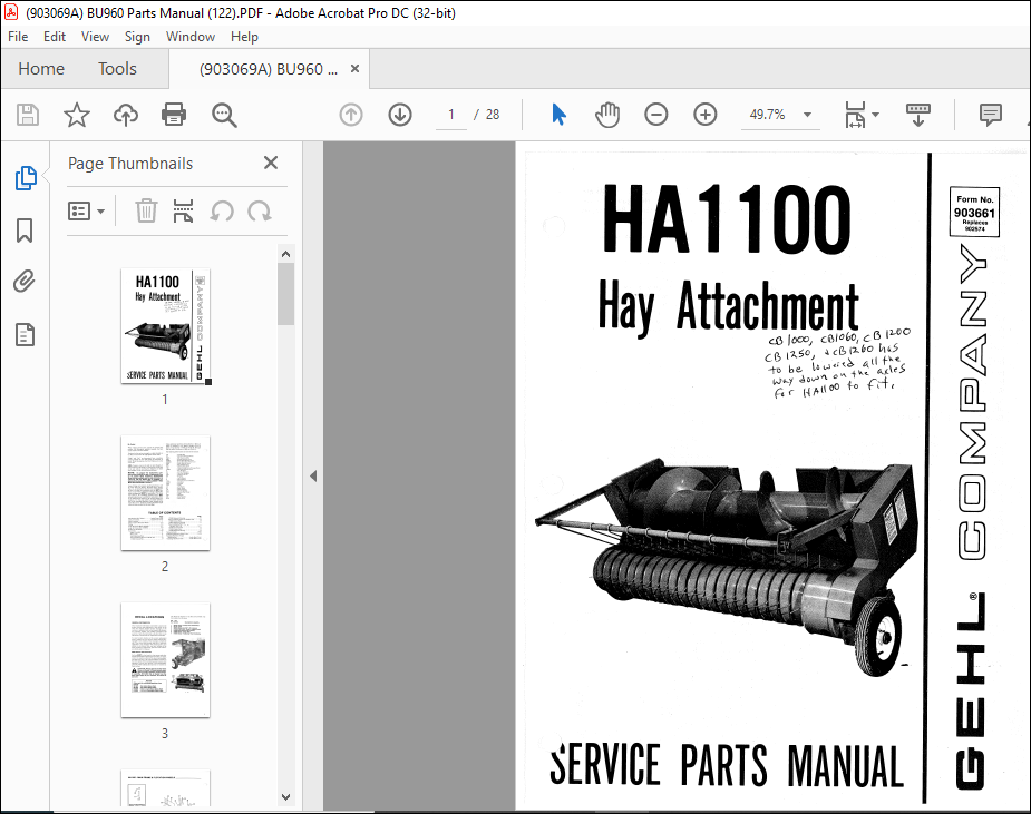
Gehl HA 1100 Hay Attachment Service Parts Manual(903661) – PDF DOWNLOAD
Gehl HA 1100 Hay Attachment Service Parts Manual(903661) – PDF DOWNLOAD
FILE DETAILS:
Language : English
Pages : 28
Downloadable : Yes
File Type : PDF
Size: 2.17 MB
TABLE OF CONTENTS:
Gehl HA 1100 Hay Attachment Service Parts Manual(903661) – PDF DOWNLOAD
Page Introduction (Mr Dealer) Inside Front Cover Table of Contents
lnside Front Cover Decai Locations I
Main Frame & Flotation Wheels 2-3
Pickup 4-5
Auger & Drives (Before SN2951) 6-7
Auger & Drives (After SN2950) 8-9
Hold-down & Shields 10
Accessories 11-18
Auger Cover Kit 11
Water Tank 11
Tank Mounting Parts 11
Tank Completing Parts for CB750j760 12
074388 Control Box 13
074390 Solenoid Housing 13
Tank Completing Parts for CBI060/ 1260 14
078008 Control Box 15
078014 Solenoid Housing 15
Tank Completing Parts for
CBI000/ 1200/ 1250 -:-‘ ‘ 16-17 –
074386 Tunnel Switch 17
074388 Control Box 18
074390 Solenoid Housing 18
Numerical Index 19-20
Technical Publication Order Forro 23-24
Standard Hardware Torque
Specifications Inside Back Cover Attaching Hardware Table Inside
Back Cover
DESCRIPTION:
Gehl HA 1100 Hay Attachment Service Parts Manual(903661) – PDF DOWNLOAD
Introduction
Mr. Dealer:
- When ordering service parts, specify the correct part number, full description, quantity required, the unit model number and serial number. Numbers for this unit are stamped on a plate located on the Main Frame below the right Quick-switch Yoke.
- “Right” and “Left” are determined from a position standing behind the unit and facing the direction of travei. Fram this position, the Drive Chains are on the “Left” side. GEHL Company reserves the right to make changes or impravements in the design or construction of any part of the unit without incurring the obligation to install such changes on any unit previously delivered.
- Grease fittings and common attaching hardware, such as Cotter Pins, Set Screws, W oodruff Keys, Screws, Nuts, etc., are included in the parts Iists, indented below the part it is (they are) associated with, but NOT illustrated, except where a particular rauting or special fastening arrangement MUST be maintained.
- The hardware listed is for mounting purposes and is NOT included when the partis ordered for replacement. Refer to the abbreviations table for the various fastener descriptions. For the part number of related fasteners, refer to the Attaching Hardware Table, located on the lnside Back Cover.
- Standard attaching hardware torque values are also pravided on the sarne page. Unless otherwise specified, aH Cap Screws or Bolts are Grade 5, cadmium or zinc plated; Hexagon Nuts for Grade 5 Cap Screws or Bolts are Grade B; Hexagon Nuts for other Cap Screws or Bolts are Grade A.
IMAGES PREVIEW OF THE MANUAL:
More products