$23
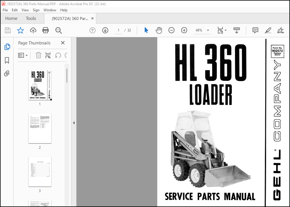
GEHL LOADER HL360 SERVICE PARTS Manual(902572) – PDF DOWNLOAD
GEHL LOADER HL360 SERVICE PARTS Manual(902572) – PDF DOWNLOAD
IMAGES PREVIEW OF THE MANUAL:
DESCRIPTION:
GEHL LOADER HL360 SERVICE PARTS Manual(902572) – PDF DOWNLOAD
- When ordering service parts, specify the correct part number, full description, quantity required, the unit model number and serial number. Numbers for this unit are stamped on a plate which is located on the left Riser below the Cross Frame Support.
- “Right” and “Left” are d~termined from a position sitting on the seat and looking forward. From this position, the Traction T-bar is the left-hand Control and the Lift/ Tilt T-bar is the right-hand Control. GEHL Company reserves the right to make changes or improvements in the design or construction of any part of the unit without incurring the obligation to install such changes on any unit previously delivered.
- : Common hardware, such as nuts, cap screws, etc. are listed in the parts list but NOT illustrated. Hardware listed, is for mounting purposes and NOT included when the part is ordered for replacement. For the part numbers of common hardware, refer to the attaching hardware table located inside the back cover
- On original Tire replacement, Company policy prohibits the sale of replacement tires for all original GEHL machinery. Replacement Wheel Sets are available and tire size information is calledout with the Wheel Sets to facilitate replacement tire selection. ALL REPLACEMENT TIRES MUST BE PURCHASED LOCALLY.
- Standard hardware torques appear in a chart at the end of the manual. Unless otherwise specified, all Cap Screws or Bolts are Grade 5, cadmium or zinc plated; Hexagon Nuts for Grade 5 Cap Screws or Bolts are Grade B; Hexagon Nuts for other Cap Screws or Bolts are Grade A.
TABLE OF CONTENTS:
GEHL LOADER HL360 SERVICE PARTS Manual(902572) – PDF DOWNLOAD
Introduction Inside Front Cover
Decal Location 2-3
Main Frame 4-5
Hydrostatic Drive Pump Idler 5
Hydraulic Motor ~ 7
Engie Controls ~
Load Arms 9
Hydrauhc 10
Hydrostatic/ Hydraulic Controls
HydrostatlCTransmlSSlOn
Gear Pumps 13
Hydraulic System
2-Spool Control
3-Spool (Auxiliary) Control Valve 17
Electrical System 18
T-Bar Console & Controls 19
Optional Auxiliary Hydraulics 21
Optional Attachments 22-23
42″ Utility Bucket 22
36″ Utility Bucket 22
60″ Light Materials Bucket 22
48″ Light Materials Bucket 22
36″ Manure Fork 23
42″ Manure Fork 23
42″ Light Materials Bucket 23
36″ Pallet Fork 23
Accessories 24
Weld-On Grapple 24
Light Kit 24
Numerical Index 25-26
Torque Specifications Inside Back Cover
Attaching Hardware Table Inside Back Cover
More products