$19
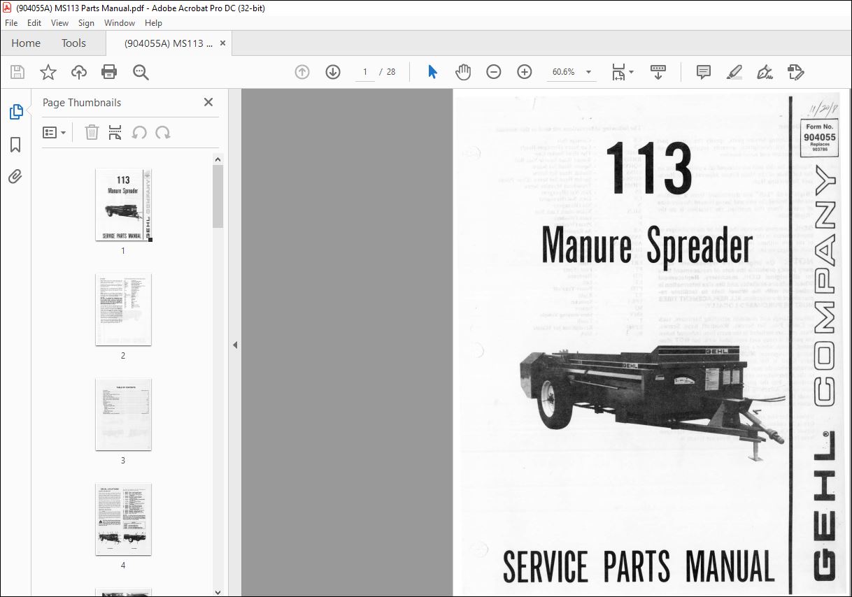
Gehl Manure Spreader 113 Service Parts Manual(904055A) – PDF DOWNLOAD
Gehl Manure Spreader 113 Service Parts Manual(904055A) – PDF DOWNLOAD
FILE DETAILS:
Gehl Manure Spreader 113 Service Parts Manual(904055A) – PDF DOWNLOAD
Language : English
Pages : 28
Downloadable : Yes
File Type : PDF
Size: 4.56 MB
IMAGES PREVIEW OF THE MANUAL:
DESCRIPTION:
Gehl Manure Spreader 113 Service Parts Manual(904055A) – PDF DOWNLOAD
Mr. Dealer:
- When ordering service pa rts. specify the correct part number, full description, quantity required, the unit model number and serial number.
- Numbers for this unit are stamped on a plate located on the Left Side of the Main Frame adjacent to the Hitchjack Supporting Hub. “Right” and “Left” are determined from a position standing behind the unit and facing toward the direction of tra vel. From this posi tion. the Gearbox is on the ” Right” sid e.
- GEHL Company res..: rvcs the ri ght to make changes or improveme nts in the design or construction of any part of the unit without incurring the obligation to install such changes on any unit previously delivered.
- Grease fittings and common attaching hardware, such as Cotter Pins, Set Screws. Woodruff Keys, Screws, Nuts, e tc., are included in the parts lists, indented below the part it is (they are) associated with, but NOT illustrated , except where a particular routing or special fastening arrangement MUST be maintained. The hardware listed is for mo unting purposes and is NOT includ ed when the part is ordered for replacement.
- Refer to the abbreviations table for the va rio us fastener descriptions. For the part number of related fastene rs, refer to the Attaching Hardware Table, located on the Inside Back Cover. Standard attaching hardware torque values are also provided on the same page. Unless otherwise specified, all Cap Screws or Bolts are Grade 5, cadmium or zinc plated; Hexagon Nuts for Grade 5 Ca p Screws or Bolts are Grade B; Hexagon Nuts for other Cap Screws or Bolts a re Grade A.
TABLE OF CONTENTS:
Gehl Manure Spreader 113 Service Parts Manual(904055A) – PDF DOWNLOAD
Introduction Inside Front Cover
Table of Contents 1
Decal Locations 2-3
Frame, Axles, Drawbar, Shields & Covers 4-5
Implement Drive Line 6
Beater Control & Indicator 7
Beater, Apron & Drives (Before SN1341) 8-9
Beater, Apron & Drives (After SN1340) 10-11
Gearbox 12-13
Telescoping Drive 14
Hitchjacks 15
Options & Accessories 16-20
Side Rails & Splash Shield 16
Endgate 17
Endgate Cylinder & Hoses 18
Litter Pan 19
Manual Trip Package 20
Numerical Index 21-22
Standard Hardware Torque Specifications Inside Back Cover
More products