$24
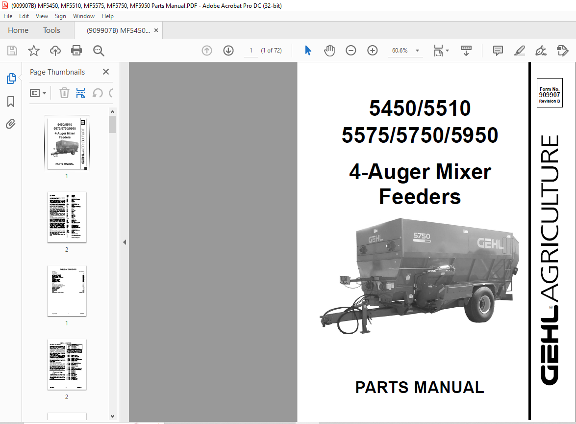
Gehl MF5450 5510 5575 5750 5950 4-Auger Mixer Feeders Parts Manual(909907B) – PDF DOWNLOAD
Gehl MF5450 5510 5575 5750 5950 4-Auger Mixer Feeders Parts Manual(909907B) – PDF DOWNLOAD
TABLE OF CONTENTS:
Gehl MF5450 5510 5575 5750 5950 4-Auger Mixer Feeders Parts Manual(909907B) – PDF DOWNLOAD
Introduction Inside Front Cover
Table of Contents 1
Decal Locations 2-7
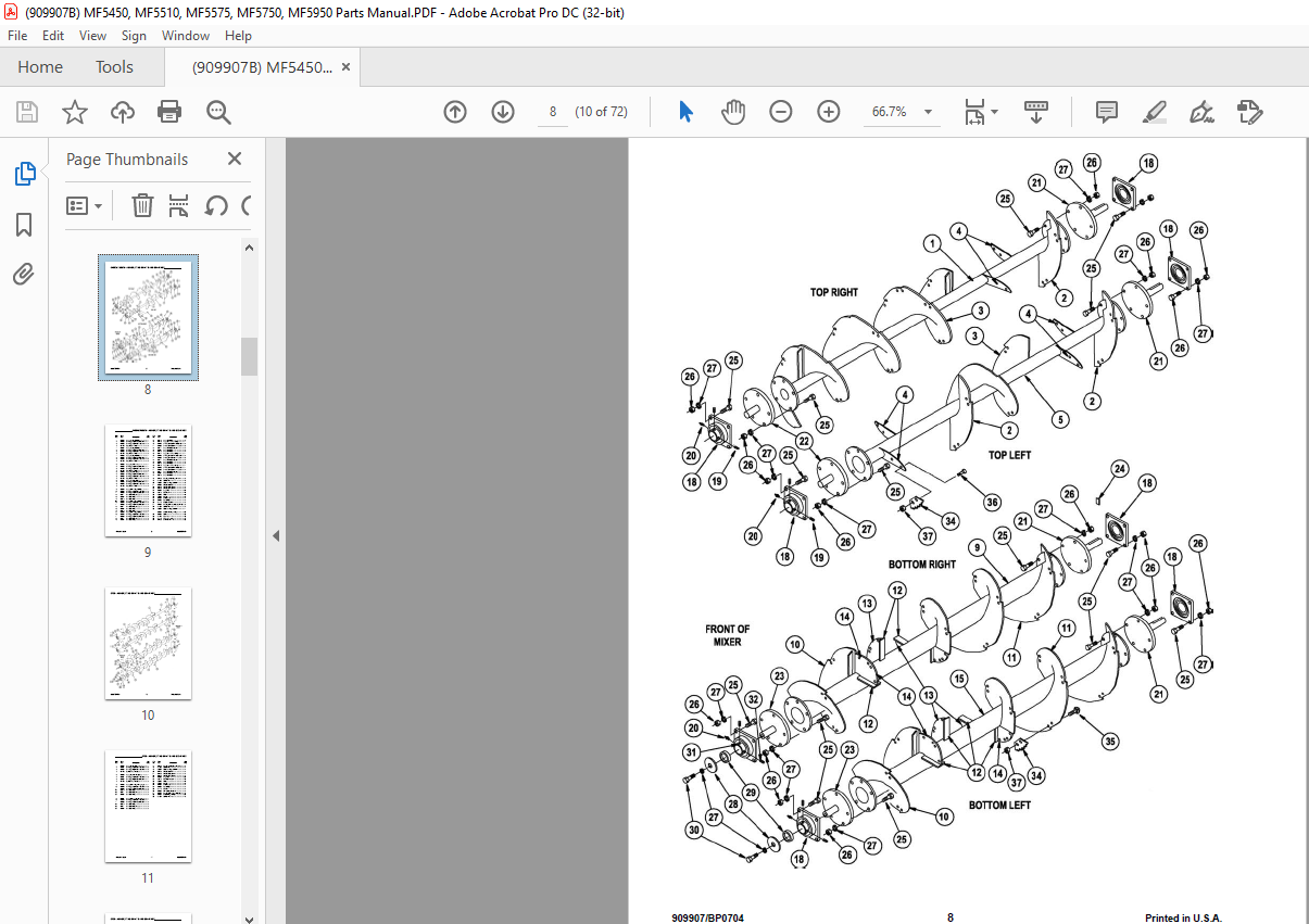
Auger, Stub Shafts & Bearings 8-13
Rear Drive 14-19
Subframe, Doors & Weighbars 20-23
Trailer Frame, Tires & Wheels 24-27
Tandem Trailer Frame, Tires & Wheels 28-29
PTO Shafts 30-33
Auger Discharge Assembly 34-39
Belt Discharge Assembly 40-41
Gravity Discharge Assembly 42-43
Discharge Doors 44-45
Lights 46-47
Scales 48-49
Truck Mounted Mechanical Drive Kit 50-51
Truck Mounted Mechanical Drive Hydraulics 52-53
Mud Flaps, Liners & Flood Lamp 54-55
Accessories – Safety Chain 56
Hydraulic Height Control 57
Alphabetical Index 58
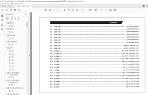
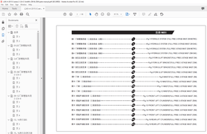
Numerical Index 59-65
Notes 66-68
Standard Hardware Torque specifications Inside Back Cover
DESCRIPTION:
Gehl MF5450 5510 5575 5750 5950 4-Auger Mixer Feeders Parts Manual(909907B) – PDF DOWNLOAD
Introduction:
When ordering service parts, please specify the correct part number, full description, quantity required, the unit model number, and serial number.
- The Mixer Feeder model and serial number are on a plate located on the left side of the main frame. “Right” and “left” are determined from a position standing behind the Mixer Feeder facing the direction of travel. From this position, the discharge gate is on the “left” side.
- GEHL Company reserves the right to make changes or improvements in the design or construction of any part of the unit without incurring the obligation to install such changes on any previously delivered units.
- Refer to the abbreviations table located on this page for the various fastener descriptions. Standard attaching hardware torque values are also provided on the inside back cover.
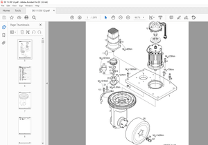
- In the exploded view parts list, reference numbers may have additional information following the reference number. A tear drop symbol will indicate an application of a “wet” product such as oil, and the number inside the tear drop will correspond to the description in the parts list. Also, a number inside a hexagon will be the torque value required, in foot-pounds, on the associated reference number. Items shown in the parts list that do not have reference numbers are shown for reference purposes only and are NOT available for purchase.
- An indent/dot system of parts listing is used in this book to indicate parts included in an assembly or subassembly. All assembly parts are listed under that assembly and are indented and dotted. All assembly parts will be included if an assembly or subassembly is ordered.
- Unless otherwise specified, all cap screws or bolts are Grade 5, cadmium, or zinc-plated. Hexagon nuts for Grade 5 screws or bolts are Grade B, while hexagon nuts for other screws or bolts are Grade A.
GENERAL INFORMATION:
- Decal location information is provided to assist in the proper selection and application of new decals, in the event the original decals become damaged or the machine is repainted. Please refer to the listing for the illustration reference number, part number, description, and quantity of each decal provided in the kit. Refer to the appropriate illustrations for replacement locations.
- To ensure proper selection for correct replacement decals, compare all of the various close-up location illustrations of the machine BEFORE starting to refinish the unit. Then, circle each pictured decal applicable to your machine, while checking off its part number in the listing. After verifying all the decals needed for replacement, set aside any unneeded decals for disposal.
IMAGES PREVIEW OF THE MANUAL:
More products